– 10 –
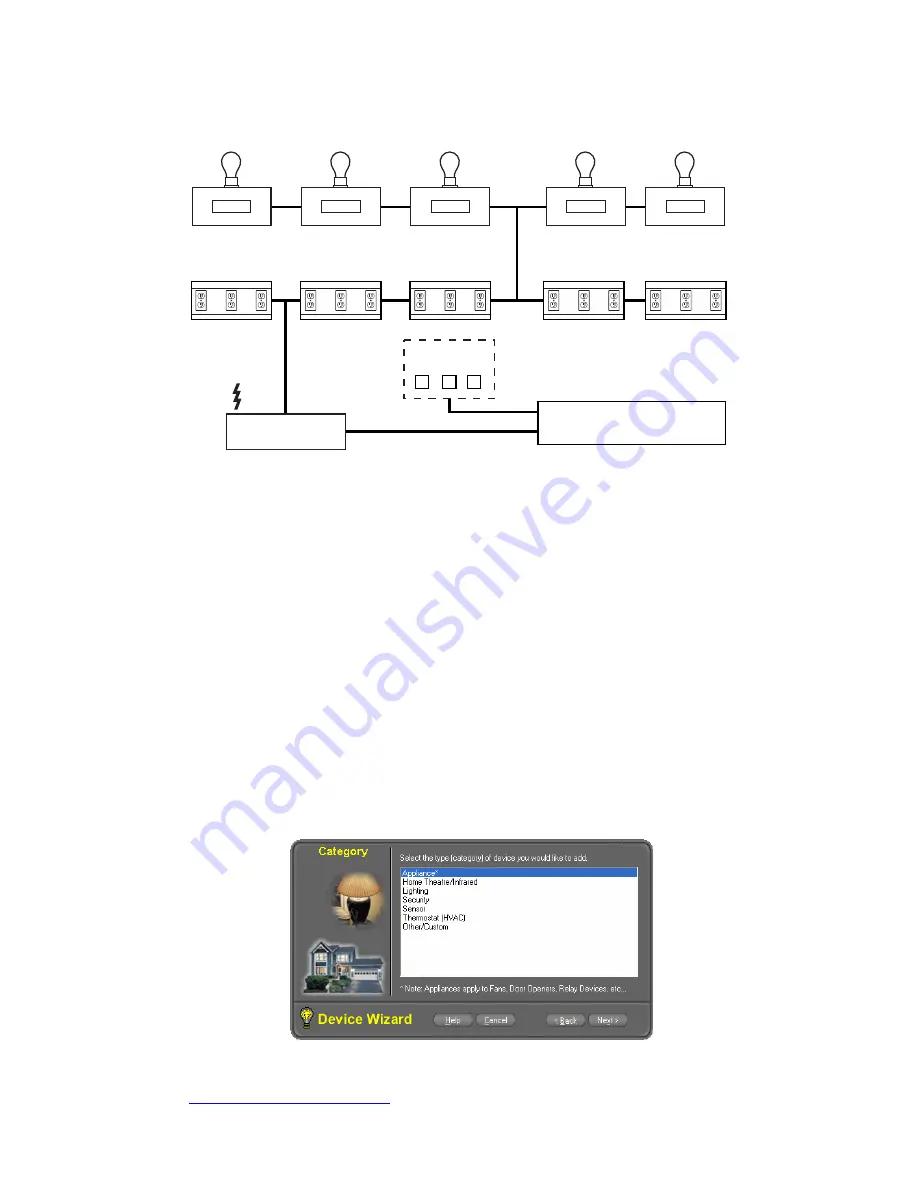
Connection Diagram of Lighting Modules
Connection Diagram of Lighting Modules is shown below
HAS-002-V0
AC OUTLETS
AC OUTLETS
AC OUTLETS
AC OUTLETS
AC OUTLETS
LAMP / APPLIANCE
MODULE
LAMP / APPLIANCE
MODULE
LAMP / APPLIANCE
MODULE
LAMP / APPLIANCE
MODULE
LAMP / APPLIANCE
MODULE
HONEYWELL HOME AUTOMATION SERVER
CONTROL INTERFACE
(WIRED / WIRELESS)
USER INTERFACE
OPTIONS
COMPUTER
MIC
PHONE
•
Lamp/Appliance Modules for the different areas in the residence can be directly
connected to AC Power with the Normal Wiring. Wireless lighting solutions are
also available. Refer to your HALPro documentation supplied with your server
for additional information. Set the device address and code as per the technology
used.
•
Connect the control interface to the server using the appropriate cables and to
right ports (RS-232, USB, and Ethernet). Refer to the installation/user manuals
supplied with the control interface for details
•
Configure the HAL Software Setting in HAL Automation Setup Screen with the
Device Name or Unit Code and House Code Details. Refer to the HALPro manual
supplied with the HALPro option that you purchased for details.
•
Create the respective device (Lamp, dimmer, switch) in the HAL Software from
the HAL Automation Device Wizard Screen as Shown Below.
•
User can set the lighting scene, grouping and modes in HAL software.
•
User interface with the Honeywell Home Automation server may be achieved by
computer, home telephone or microphone.
For detailed instructions on how to configure Schedules, Modes and Tasks please
refer to HAL Manual supplied with the HALPro option that you purchased or
www.automatedliving.com
web site.


