


HA20 2-Channel Controller
HA20 Technical Manual
2-8
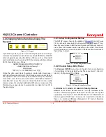
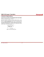
[AND column selections] ANDED WITH [OR column selections] = relay
activation.
For example, if Ch1A1 & Ch2A1 are selected in the AND column and
Ch1A2 & Ch2A2 are selected in the OR column, the logic equation
is [Ch1A1 AND Ch2A1] ANDED WITH [Ch1A2 OR Ch2A2]. This
requires both A1s along with either A2 to activate the relay.
Figure 2-10. Set Relay Logic
• Failsafe
controls relay activation for the common relays. Failsafe
ON causes these relays to de-energize during alarm conditions
and energize when there is no alarm.
With Failsafe active, a power failure forces the relay contact to
the alarm position.
• Horn
controls how activating this relay will affect the horn driver
circuit connected to J2 on the motherboard. Choices are NO,
STEADY or PULSE (Ex.: The horn can be set to
Pulse
for
warning. alarm levels and set to
Steady
for high alarm levels. Thus,
personnel can know which alarm level is present by based on the
pulsing or steady horn).
• Turning
Acknowledge
ON (not allowed on Relay 1) allows
Relay 2 to be deactivated by an Alarm Reset during alarm
conditions. This is useful if another audible device is being driven
by the relay. The acknowledge feature is not available for Relay
1 since it is often used for driving a warning light and Relay 2
for driving a horn. Using Acknowledge (thus deactivating) when
horn and light are activated could be dangerous since this
deactivates both and no indication of the High alarm remains.
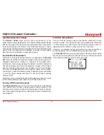
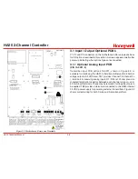
2.3.2 Horn / Piezo Menu
• The HA20 display PCB is equipped with a small audible piezo
(NEMA 4X housing only) that chirps when keys are pressed
providing an audible feedback to the operator. It also may be
set to audibly indicate alarm conditions by selecting YES in the
Piezo On
menu option (Figure 2-11). This piezo will then mimic
the Horn settings menus described in
Section 2.3.1
.
• The Horn ACK menu item determines if the Horn Driver output
may be acknowledged by an Alarm Reset. YES causes an
Alarm Reset to silence the horn even though an alarm condition
remains active.
Figure 2-11. Horn/Piezo Menu
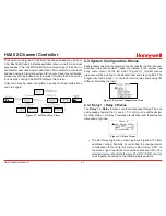
2.3.3 Comm Port Menu
The system
Comm Port
menu allows setting RTU address for the
optional slave Modbus serial port. This slave port may be used to
transfer HA20 data to a host device such as a PC, PLC, DCS or even
another Honeywell Analytics Controllers. The slave port is addressable,
allowing many HA20 controllers to be connected to a single RS-485
cable.
Figure 2-12. Communication Port Menu
Summary of Contents for HA20
Page 6: ...HA20 2 Channel Controller HA20 Technical Manual v ...
Page 7: ...HA20 2 Channel Controller HA20 Technical Manual 1 1 1 General Description ...
Page 12: ...HA20 2 Channel Controller HA20 Technical Manual 2 1 2 Operation ...
Page 22: ...HA20 2 Channel Controller HA20 Technical Manual 3 1 3 Motherboard Interface PCB ...
Page 30: ...HA20 2 Channel Controller HA20 Technical Manual 3 9 ...
Page 31: ...HA20 2 Channel Controller HA20 Technical Manual 3 10 ...
Page 32: ...HA20 2 Channel Controller HA20 Technical Manual 4 1 4 Enclosures ...
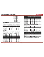
Page 35: ...HA40 4 Channel Controller HA40 Technical Manual 5 1 5 Parts List ...
Page 37: ...HA20 2 Channel Controller HA20 Technical Manual 6 1 6 Specifications ...
Page 39: ...HA20 2 Channel Controller HA20 Technical Manual 7 1 7 Warranty ...


