

GW-1000-WE / GW-1000-NWE GATEWAY
31-00425 | Rev.10-20
Part Number: 32348979-001
2
WARNING
Electrical Shock Hazard.
Can cause severe injury, death or property
damage.
Disconnect the power supply before beginning
installation to prevent electrical shock and
equipment damage. More than one power supply
may have to be disconnected.
When Installing This Product
1.
Read these instructions carefully. Failure to follow
them could damage the product or cause a hazard
-
ous condition.
2.
Check the ratings given in the instructions and
marked on the product to make sure the product is
suitable for your application.
3.
Installer must be a trained, experienced service tech
-
nician.
4.
After installation is complete, check the product
operation.
5.
Be sure wiring complies with all applicable codes,
ordinances and regulations.
Regulation (EC) No 1907/2006
According to Article 33 of REACH Regulation, be informed
that this product may contain components with lead (CAS:
7439-92-1) content above the threshold level of 0.1% by
weight.
INTRODUCTION
This document contains mounting instructions for GW-
1000-WE and GW-1000-NWE Gateways and its
accessories. These Gateways can be mounted on the wall,
panel, and DIN rail.
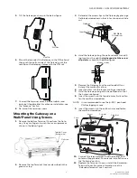
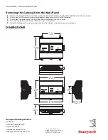
Mounting the Gateway on a
Wall/Panel Using DIN Rail
1.
Mount the DIN rail on the wall/panel by using screws.
2.
Remove the bottom Terminal Cover from the Gate
-
way. Use your fingers to push the cover upwards as
shown in the below figure.
3.
Remove the top Terminal Cover as described in the
previous step.
4.
Hold the Gateway in an orientation such that the red
clip is facing downwards and towards the DIN rail.
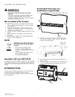
WEEE
WEEE Directive 2012/19/EC Waste
Electrical and Electronic Equipment
Directive
• At the end of the product life,
dispose of the packaging and
product in an appropriate recycling
center.
• Do not dispose of the device with
the usual domestic refuse.
• Do not burn the device.
Screw
Panel/Wall
DIN Rail
Terminal Cover
(Bottom side)
Up Arrow
GW-1000-NWE
Gateway
DIN Rail
Red Clip
POWER
RS485
CH2-
FGND
+