


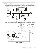


ANN-BUS Devices
Installation
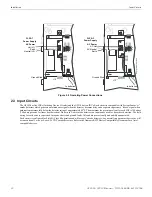
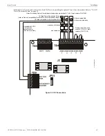
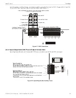
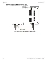
2.8 ANN-BUS Devices
Guidelines
•
A variety of optional annunciation devices can be connected to an ANN-BUS communication circuit. ANN Series devices can be
connected to the primary communication circuit (EIA-485) terminals on TB3. A secondary communication circuit (EIA-485) for
these devices is available at TB1 on the ANN-SEC card.
•
When using one ANN-BUS circuit, up to eight (8) annunciators can be supported.
•
When using both ANN-BUS communication circuits, the primary circuit supports up to three (3) annunciators and the secondary
circuit supports up to (5) annunciators.
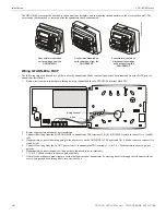
Compatible devices include:
– GFANN-80 LCD Annunciator
– GFANN-LED Annunciator Module
– GFANN-RLY Relay Module (can be mounted in the FACP chassis)
•
When operating two ANN-BUS circuits, only one ANN-S/PG Printer module can be used in the system.
•
The panel is capable of operating a primary ANN-BUS (TB3) and a secondary ANN-BUS (TB1 on ANN-SEC card)
simultaneously.
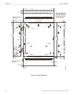
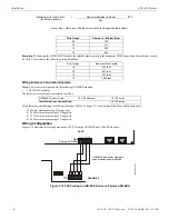
2.8.1 ANN-BUS Wiring
This section contains information on calculating ANN-BUS wire distances and the types of wiring configurations (Class B). The length
of the 4-conductor wire run is governed by the power pair loading as described below.
Calculating Wiring Distance for ANN-BUS Modules
The following instructions will guide the installer in determining the type of wire and the maximum wiring distance that can be used
with FACP ANN-BUS accessory modules.
To calculate the wire gauge that must be used to connect ANN-BUS modules to the FACP, it is necessary to calculate the total worst case
current draw for all modules on a single 4-conductor bus. The total worst case current draw is calculated by adding the individual worst
case currents for each module. The individual worst case values are shown in the following table:
After calculating the total worst case current draw, Table 2.2 specifies the maximum distance the modules can be located from the FACP
on a single wire run. The table ensures 6.0 volts of line drop maximum. In general, the wire length is limited by resistance, but for
heavier wire gauges, capacitance is the limiting factor.
These cases are marked in the chart with an asterisk (*). Maximum length can never be more than 6,000 feet (1,800 m), regardless of
gauge used. The formula used to generate this chart is shown in the note below.
The following formulas were used to generate the wire distance chart:
!
WARNING: RISK OF ELECTRICAL SHOCK
DISCONNECT ALL SOURCES OF POWER (AC AND DC) BEFORE INSTALLING OR REMOVING ANY MODULES OR
WIRING.
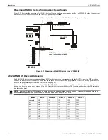
Model Number
Worst Case Current Draw
1
1
Total worst case current draw on a single ANN-BUS cannot exceed 0.5 amp
.
GFANN-80 LCD Annunciator
0.040 amps
GFANN-LED Annunciator Module
0.068 amps
GFANN-RLY Relay Module
0.075 amps
Table 2.1
24 VDC Power Wiring Distance: ANN-BUS Modules to FACP
Total Worst Case Current
Draw (amps)
22 Gauge
18 Gauge
16 Gauge
14 Gauge
0.100
1,852 ft.
4,688 ft.
* 6,000 ft.
* 6,000 ft.
0.200
926 ft.
2,344 ft.
3,731 ft.
5,906 ft.
0.300
617 ft.
1,563 ft.
2,488 ft.
3,937 ft.
0.400
463 ft.
1,172 ft.
1,866 ft.
2,953 ft.
0.500
370 ft.
938 ft.
1,493 ft.
2,362 ft.
Table 2.2 Wiring Distances
Maximum Resistance (Ohms)
=
6.0 Volts
Total Worst Case Current Draw (amps)
GF505 & GF510 Manual —
P/N 53164:B5 6/12/2018
33