
Honeywell Life Safety AS, Po. Box 3514, N-3007 Drammen, Norway
http://www.hls-nordic.com
GB
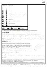
Mounting Methods
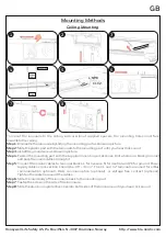
Ceiling Mounting
2
3
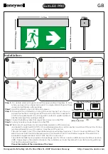
To mount the luminaire to the ceiling, with or wihout supplied spacers, the mounting holes must face
towards to the ceiling.
Step 1:
Dismantle the luminaire by sliding the mounting part as shown in picture.
Step 2:
Slide the plastic part with the terminals to the mounting part, until you hear click sound.
Step 3:
Install the ground wire as shown in picture.
Step 4:
Fasten the mounting part with the supplied mounting accessories. Drill a hole on a black grommet
and pass the mains cables through it.
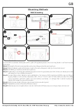
Step 5:
Connect the mains cables to terminal blocks: L for live wire, N for neutral and PE for ground. Power
2
supply cables cross section should be 0.8 - 3 mm . The C1 and C2 terminals are used for elBus
communication optional), DALI communication (optional), or voltage free contact (optional).
Tighten the cable tie around the cables.
Step 6:
Slide the main body of the luminaire back to the mounting part.
Step 8:
Slide the aluminium protective covers to both sides of the luminaire, until you hear click sound.
Step 7:
Fasten the screw on the side of the luminaire.
1
8
Screw
Wall Plug
Power
Cable
L NPE
C1C2
6
4
7
5