


Honeywell
Heating & Cooling Appliance Controls
Title: Functional description
S4965A3025
Doc.:
S4965A3025E20
Description Sign.
E.C.N.
Date
Rev.
First issue
M.Matiasko
01-Sep-2015
A
Page
21/22
IMPORTANT
Wiring must be in accordance with local regulations.
The appliance manufacturer’s instructions should always be followed when provided. If such instructions are not provided
see the connection diagrams for typical systems.
Before installing or replacing any control check that type number is correct for the application.
Ensure combustion chamber is free of gas before start up.
Conduct a thorough check out when installation is completed.
At the first start the boiler control can be in lock-out; depress reset button to free control.
CAUTION
Do not connect the boiler control to power supply when it is not connected to the gas control.
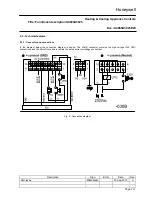
Wiring
Use lead wire which can withstand at least 105 °C ambient.
Use lead wire which is proven against moisture.
Wiring between boiler control and spark sensing probe should have good quality insulation, suitable for the
temperatures encountered.
Gas valve should be connected to protective earth.
Fusing
Ext. fuse 2A slow sand filled.
Spark gap
Max. allowable spark gap 3.5 mm (recommended 3 mm.)
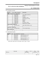
10.3 - Cables and wirings
Respect maximum connection cables length requirements.
Use connection cables with appropriate insulation, working temperatures and moisture resistance.
Plan separate routes for cables that connect loads at low voltage (SELV) and loads at mains voltage (HT). Avoid
connecting high and low voltage cables together.
The ignition cable must be laid so that it is separate from all the other connection cables. Use short connections to
minimize the emission of electromagnetic interference.
The flame sensor/ignition output is not protected against the danger of electric shocks. The connection cable and
flame sensor must both be protected against direct contact.
Do not use multiple cables to connect more than one external device using a single cable. The use of a multiple
cable to attach several external devices supplied with high and low voltage is expressly prohibited.
The flame control earth terminal and/or the earth lead of the second spark generator output must be connected to
the metal earth of the burner by the shortest route and the path must be different from that followed by the other
wiring.
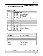
10.4 - Ionization current check
The current value must be greater than the specified minimum.
If the ionization current is too low, check that the electrode is fully immersed in the flame and that the burner and
the flame control are properly connected to the protection earth.