


26
Installation and Setup
Note
If your installation involves a 24V AC power source, then please wait
approximately 60 seconds after connecting to a power source for video to
appear on the local video out.
2. Connect the supplied video cable to the local video out connector to view the video
signal on a standard monitor (see
below to connect a local video monitor).
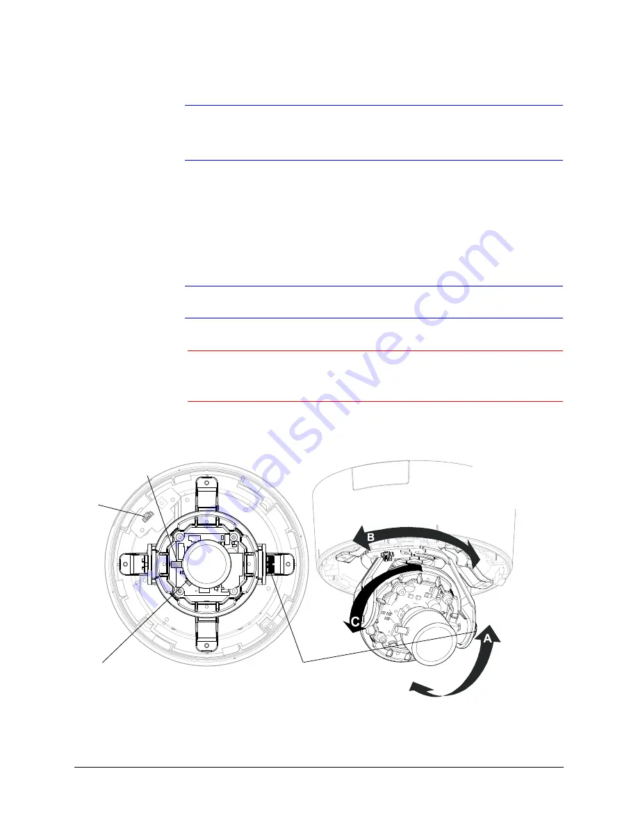
3. Loosen the setscrew that locks the gimbal assembly in place (see
adjust the horizontal rotation.
4. Adjust the gimbal assembly to the desired view.
5. Re-tighten the locking screw to lock the gimbal assembly in place.
Note
illustrates the ways in which you can adjust your camera.
Caution
Adjust the camera field of view only by moving the gimbal. Do not
move the camera lens to adjust the camera field of view as this might
result in irreparable damage.
Figure 2-8
Gimbal Adjustment
Angle view
Top view
Setscrew (loosen to
adjust horizontal
rotation)
Loosen set screw to adjust
Tilt Rotation (A)
Set focal length
(bottom)
Legend
A = Tilt rotation
B = Horizontal rotation
C = Pan rotation
Local
video
out
Summary of Contents for EQUIP HD3MDIH
Page 8: ...8 Tables ...
Page 14: ...14 Introduction ...
Page 28: ...28 Installation and Setup ...
Page 42: ...42 Installing the Honeywell IP Utility and Web Client Software ...
Page 64: ...64 IP Camera Web Client ...
Page 66: ...66 Surface Mounting Template ...
Page 79: ......