Emergency Command Center Manual —
P/N LS10001-000FL-E:G 5/3/2016
37
Output Circuits
Installation
2.6.2 Speaker Circuits
•
One Speaker Circuit Style Y (Class B) or Style Z (Class A) standard
•
Two Speaker Circuits Style Y (Class B) or Style Z (Class A) with ECC-50-25/70V
•
Four Speaker Circuits Style Z (Class B) or Style Z (Class A) or Style Y with ECC-CE6
•
Eight Speaker Circuits Style Z (Class B) or Style Z (Class A) or Style Y with ECC-50W-
25/70V and ECC-CE6
The integral amplifier and optional amplifier each provide audio for one Speaker Circuit. The cir-
cuit can be wired Style Y (Class B) or Style Z (Class A). Each supervised and power-limited
(Class 2) circuit is capable of 50 watts of power. Refer to the Fire•Lite Device Compatibility Docu-
ment for a listing of compatible speakers.
Shielded cable is not required, however, shielded cable will reduce RFI/EMI emissions and suscep-
tibility. For additional information, refer to “Wiring Requirements” on page 101.
!
CAUTION:
OBSERVE POLARITY
MATCH PROPER POLARITY CONNECTIONS TO FIELD WIRING AND SPEAKERS. POLARITY
SHOWN IS IN THE STANDBY AND ALARM CONDITIONS.
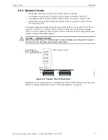
TB20
TB21
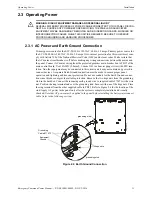
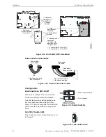
Figure 2.15 Speaker Circuit Connections
Style Z (Class A) Circuit
ELR required for
Style Y - Class B only
15K, 1 watt, P/N:ELR-15K
Shield
e
c
c
c
k
t1
.w
m
f
Summary of Contents for ECC-50/100
Page 83: ...Emergency Command Center Manual P N LS10001 000FL E G 5 3 2016 83 Notes ...
Page 95: ...Emergency Command Center Manual P N LS10001 000FL E G 5 3 2016 95 Notes ...
Page 102: ...102 Emergency Command Center Manual P N LS10001 000FL E G 5 3 2016 Notes ...
Page 106: ...106 Emergency Command Center Manual P N LS10001 000FL E G 5 3 2016 Slide in Labels ...
Page 108: ...108 Emergency Command Center Manual P N LS10001 000FL E G 5 3 2016 Slide in Labels ...
Page 114: ...Cut along dotted line ...


