background image

Operation

42

UDC3300 Basic Model: DC330B User Manual

5/00

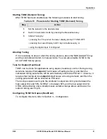
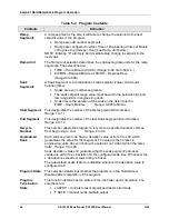
4.3 Start-up Procedure

Table 4-3   Procedure for Starting Up the Controller

Step

Operation

Press

Action

1

Select
manual mode

MANUAL

AUTO

until “MAN” indicator is ON.
The controller is in manual mode.

2

Adjust the
output

 or 

to adjust the output value and ensure that the final control
element is functioning correctly.

Upper Display: PV value
Lower Display: OUT and the output value in %

3

Enter the
local setpoint

LOWER

DISPLAY

Upper Display: PV Value
Lower Display: SP and the local setpoint value

 or 

to adjust the local setpoint to the value at which you want
the process variable maintained.

The local setpoint cannot be changed if the Setpoint
Ramp function is running. “R” appears in the upper
display.

4

Select
automatic
mode

MANUAL

AUTO

until “A” indicator is ON.
The controller is in Automatic mode.

The controller will automatically adjust the output to
maintain the process variable at setpoint, if the controller
is properly tuned.

5

Tune the
controller

SET UP

Tuning will be required on the first startup. First enable
“TUNE” selection in the Accutune Group.

Refer to Tuning Set Up group to ensure that the proper
selections for PROP BD or GAIN, RATE MIN, and RSET
MIN, or RSET RPM have been entered.

Use Accutune to tune the controller as follows:

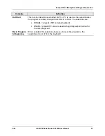
1.  Adjust setpoint to the desired value.

2.  Switch to Automatic mode by pressing the

MANUAL/AUTO key.

3.  Initiate Tuning by:

  Pressing the up arrow key when the lower display

prompt shows TUNE-OFF, or

  Pressing the LOWER DISPLAY and Up arrow

keys simultaneously, or…

  Using the Digital Input, if configured.

If it is necessary to stop or abort the tuning process, press
the MANUAL/AUTO key and the controller will return to
manual mode.

Summary of Contents for DC3300

Page 1: ...Sensing and Control UDC3300 Basic Model DC330B User Manual 51 52 25 78 5 00 ...

Page 2: ...and is in lieu of all other warranties expressed or implied including those of merchantability and fitness for a particular purpose Specifications may change without notice The information we supply is believed to be accurate and reliable as of this printing However we assume no responsibility for its use While we provide application assistance personally through our literature and the Honeywell w...

Page 3: ... sites that will be of interest to our customers Honeywell Organization WWW Address URL Corporate http www honeywell com Sensing and Control http www honeywell com sensing International http www honeywell com Business global asp Telephone Contact us by telephone at the numbers listed below Organization Phone Number United States and Canada Honeywell 1 800 423 9883 610 641 3610 Tech Support 1 888 4...

Page 4: ... Discharge ESD hazards Observe precautions for handling electrostatic sensitive devices Protective Earth PE terminal Provided for connection of the protective earth green or green yellow supply system conductor Functional earth terminal Used for non safety purposes such as noise immunity improvement NOTE This connection shall be bonded to protective earth at the source of supply in accordance with...

Page 5: ...ata Set Up Group 26 3 7 Output Algorithm Parameters Set Up Group 28 3 8 Input 1 Parameters Set Up Group 29 3 9 Input 2 Parameters Set Up Group 30 3 10 Loop 1 Control Parameters Set Up Group 31 3 11 Options Set Up Group 33 3 12 Communications Set Up Group 34 3 13 Alarms Set Up Group 36 3 14 Display Parameters Set Up Group 38 3 15 Calibration Group 38 3 16 Status Group 38 4 OPERATION 39 4 1 How to P...

Page 6: ...a Security Code 52 5 SETPOINT RATE RAMP SOAK PROGRAM OPERATION 53 5 1 Setpoint Ramp Rate 53 5 2 Single Setpoint Ramp 53 5 3 Setpoint Ramp Soak Programming Option 55 6 APPENDIX A ENVIRONMENTAL AND OPERATING CONDITIONS 63 7 APPENDIX B MODEL SELECTION GUIDE 65 8 APPENDIX C CONFIGURATION RECORD SHEET 67 9 APPENDIX D POSITION PROPORTIONAL CALIBRATION 69 9 1 Position Proportional Control Output Calibrat...

Page 7: ...isplay Group Function Prompts______________________________________38 Table 4 1 Lower Display Key Parameter Prompts__________________________________40 Table 4 2 Error Messages ____________________________________________________41 Table 4 3 Procedure for Starting Up the Controller _________________________________42 Table 4 4 Setpoint Selection Indication _________________________________________...

Page 8: ...x Position Proportional or Three Position Step Control ____________________________12 Figure 2 11 Auxiliary Output and Three Relay Output ______________________________12 Figure 2 12 Position Proportional Output or Three Position Step Models DC330X EE XXX X2 DC330X AA XXX X2 ____________________________13 Figure 2 13 Auxiliary Output Connections Models DC330X XX 2XX DC330X XX 5XX _________________...

Page 9: ...ECT RUN HOLD DI 3300 SP 3300 Indicator definition when lit ALM Alarm conditions exist DI Digital input active OUT Control relay 1 or 2 on Upper Display six characters Normal Operation four digits dedicated to display the process variable Configuration Mode displays parameter value or selection Lower Display eight characters Normal Operation displays operating parameters and values Configuration Mo...

Page 10: ...ON LOOP 1 2 Used in conjunction with the SET UP key to select the individual functions of a selected Configuration Set Up group LOWER DISPLAY Selects an operating parameter to be shown in the lower display MANUAL AUTO Alternately selects AUTO or MAN SETPOINT SELECT Hold key down to cycle through configured setpoints RUN HOLD Alternate action switch initiates or holds the Setpoint Ramp or Setpoint ...

Page 11: ...pplied Adequate access space must be available at the back of the panel for installation and servicing activities Panel Cutout 96 3 780 24 945 Max Panel Thickness 10 394 Max 2 5 82 147 3 21 6 850 093 2 4 with optional rear cover 90 7 3 57 24152 0 008 92 3 622 0 03 0 0 0 0 0 008 92 3 622 0 03 0 0 0 0 FUNCTION L1 L2 LOWER DISPLAY MANUAL AUTO SETPOINT SELECT SET UP RUN HOLD 96 3 780 Figure 2 1 Dimens...

Page 12: ...shall install this controller in an enclosure that limits OPERATOR access to the rear terminals Controller Grounding PROTECTIVE BONDING grounding of this controller and the enclosure in which it is installed shall be in accordance with National and local electrical codes To minimize electrical noise and transients that may adversely affect the system supplementary bonding of the controller enclosu...

Page 13: ...oise Your controller has built in circuits to reduce the effect of electrical noise from various sources Be sure to separate external wiring into bundles see Table 2 1 and route the individual bundles through separate conduits or metal trays ATTENTION For installation where high EMI RFI noise cannot be avoided we recommend you use shielded twisted pair wires for the signals in bundle 2 Table 2 1 P...

Page 14: ...e Figure 2 12 For Control and Alarm Relay Contact information See Tables 2 3 and 2 4 Digital Inputs Terminals See Figure 2 14 AC Line Voltage Terminals See Figure 2 4 Input 2 Terminals See Figure 2 5 Input 1 Terminals See Figure 2 5 10 11 12 13 14 15 16 17 Communications Terminals See Figure 2 15 Transmitter Power for 4 20 mA 2 wire Transmitters Using Alarm 2 Output See Figure 2 16 Using Auxiliary...

Page 15: ...ely damage the controller and is a fire and smoke hazard When applying power to multiple instruments make sure that sufficient current is supplied Otherwise the instruments may not start up normally due to the voltage drop caused by the in rush current L1 L2 N 22 Ground Hot Neutral AC DC Line Voltage 1 2 1 PROTECTIVE BONDING grounding of this controller and the enclosure in which it is installed s...

Page 16: ...able 2 2 for Input 2 Jumper selections 25 26 27 Use Thermocouple extension wire only Thermocouple RTD Carbon mV or Volts except 0 10 Volts mV or Volt source 0 10 Volts 4 20 milliamps R 1 2 3 0 10 Volt source 100K 100K Power Supply Xmitter 250Ω 1 Remove screw and install C J on the R terminal connect tang to terminal 2 25 26 27 R 25 26 27 R 25 26 27 R 1 25 26 27 R 1 INPUT 1 3 2 When installing the ...

Page 17: ...3 and Table 2 4 Figure 2 6 shows the Output and Alarm wiring connections for models with Electromechanical Relay Output 1 Alarm 2 is not available with Time Proportional Duplex or Three Position Step Control or Position Proportional Control or Current Time Duplex 2 Electromechanical relays are rated at 5 Amps 120Vac or 30 Vdc and 2 5 Amps at 240 Vac Customer should size fuses accordingly Use FastB...

Page 18: ...s are rated at 5 Amps 120Vac or 30 Vdc and 2 5 Amps at 240 Vac Customer should size fuses accordingly Use Fast Blo fuses only WARNING Only connect Vac to solid state relays 4 Alarm Relay 1 Output Relay 1 To terminal 7 or 9 Output Relay 2 AC Load Supply Power Relay Load Dummy Resistor N O N O AC Load Supply Power Relay Load Dummy Resistor 1 1 3 3 2 1 2 3 4 5 6 7 8 9 N O N C AC Load Supply Power Ala...

Page 19: ...pply will damage the controller Alarm 2 not available with Time Proportional Duplex or Three Position Step Control or Position Proportional control 1 1 1 1 1 1 2 2 1 2 1 2 3 4 5 6 7 8 9 N C N C N O N O 1 2 3 4 5 6 7 8 9 N C N C N O N O 1 2 3 4 5 6 7 8 9 N C N O 1 2 3 4 5 6 7 8 9 N C N O Alarm Relay 2 Load Load Supply Power Alarm Relay 1 Load Load Supply Power Alarm Relay 2 Load Load Supply Power A...

Page 20: ...Use Fast Blo fuses only Relays are NOT available on DC330X C0 1 1 1 Figure 2 10 Current Output Current Time Duplex Time Current Duplex Position Proportional or Three Position Step Control Figure 2 11 shows the Output and Alarm wiring connections for models with a Current Output Auxiliary Output and three Relay Outputs Model DC330X EE 2XX Alarm Relay 1 16 17 N O To terminal 7 or 9 Relay Load Load S...

Page 21: ...tor Connect shield to ground at one end only Neutral Hot Motor Power Supply Op en Cl os ed To terminal 7 or 9 Op en Alarm Relay 1 Output Relay 1 Output Relay 2 N C N C N O N O N C N O Cl os ed Wi pe 2 1 1 2 3 Alarm 2 is not available with Position Proportional output or Three Position Step control Do not run slidewire cable in the same conduit as AC power Electrical noise suppression may be requir...

Page 22: ...put for Output 1 heat ATTENTION Both current outputs control and auxiliary are isolated from each other case ground and all inputs Figure 2 13 Auxiliary Output Connections Models DC330X XX 2XX DC330X XX 5XX Digital Inputs 10 11 12 Digital Input Switch 1 Digital Input Switch 2 Connect shield to ground at one end only Switch Common Figure 2 14 Digital Inputs Connections Model DC330X XX XX3 ...

Page 23: ... Option Connections 13 14 15 16 17 Master TX SHD TX RX RX Do not mix half and full duplex wiring Do not run these lines in the same conduit as AC power CAUTION 13 14 15 Master TX RX SHD TX RX ASCII or MODBUS RS422 485 HALF DUPLEX To Other Communication Instruments maximum 31 SHD TX RX TX RX ASCII RS422 485 FULL DUPLEX RX SHD RX TX TX 120 Ohm Resistor To Other Communication Instruments maximum 31 1...

Page 24: ...6 Transmitter Power for 4 20 mA 2 wire Transmitter Using Open Collector Alarm 2 Output Model DC330X XT XXX Transmitter power for 4 20 mA 20 wire Transmitter Using Auxiliary Output The wiring diagram example shown in Figure 2 17 Model DC330X XX 2XX or DC330X XX 5XX provides 30 Vdc at terminal 16 with the capability of driving up to 22 mA If the transmitter terminal voltage must be limited to less t...

Page 25: ... Closed Open Off On Alarm Relays ATTENTION Alarms relays are designed to operate in a failsafe mode i e de energized during alarm state This results in alarm actuation when power is OFF or when initially applied until the unit completes self diagnostics If the unit loses power the alarms will function Table 2 4 Alarm Relay Contact Information Variable NOT in Alarm State Variable in Alarm State Uni...

Page 26: ...Installation 18 UDC3300 Basic Model DC330B User Manual 5 00 ...

Page 27: ...hy As you will see the configuration data is divided into 12 main Set Up groups plus prompts for calibration and prompts that show the status of the continuous background tests that are being performed Figure 3 1 Prompt Hierarchy Set Up Group Function Prompts TUNING PROP BD or GAIN GAINVALn RATE MIN RSET MIN or RSET RPM MAN RSET PROPBD2 or GAIN 2 RATE2MIN RSET2MIN or RSET2RPM CYC SEC or CYC SX3 CY...

Page 28: ...LoLIM I Hi LIM I Lo LIM DROPOFF DEADBAND OUT HYST FAILMODE FAILSAFE MAN OUT AUTO OUT PBorGAIN MINorRPM OPTIONS AUX OUT 4 mA VAL 20mA VAL DIG IN 1 DIG1 COM DIG IN 2 DIG2 COM COM ComSTATE Com ADDR SHEDENAB SHEDTIME PARITY BAUD DUPLEX WSFLOAT TXDELAY SHEDMODE SHEDSP UNITS CSP RATO CSP BIAS LOOPBACK ALARMS A1S1 VAL A1S2 VAL A2S1 VAL A2S2 VAL A1S1TYPE A1S2 TYPE A2S1TYPE A2S2TYPE A1S1 H L A1S1 EV A1S2 H...

Page 29: ...e Then proceed to the next step 3 Select a Function parameter FUNCTION Upper Display Shows the current value or selection for the first Function prompt of the selected Set Up group Lower Display Shows the first Function prompt within that Set Up group Sequentially displays the other function prompts of the selected Set Up group Stop at the function prompt that you want to change then proceed to th...

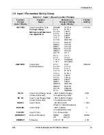
Page 30: ...uling when enabled Read Only RATE MIN Rate in Minutes 0 00 to 10 00 minutes 0 00 RSET MIN or RSET RPM Reset in minutes repeat or Reset in repeats minute 0 02 to 50 00 1 00 MAN RSET Manual Reset 100 to 100 output 0 PROPBD2 or GAIN 2 Proportional Band 2 or Gain 2 0 1 to 9999 0 001 to 1000 1 000 RATE2MIN Rate 2 in Minutes 0 00 to 10 00 minutes 0 00 RSET2MIN or RSET2RPM Reset 2 in minutes repeat or Re...

Page 31: ...nction Name Selections or Range of Setting Upper Display Factory Setting LOCKOUT Configuration Lockout NONE CALIB CONF VIEW MAX CALIB AUTO MAN Manual Auto Key Lockout DISABL ENABLE ENABLE SP SEL Setpoint Select Key Lockout DISABL ENABLE ENABLE RUN HOLD Run Hold Key Lockout DISABL ENABLE ENABLE ...

Page 32: ...Programming are disabled SP RATE Setpoint Rate DISABL ENABLE DISABL EU HR UP Rate Up Value for Loop 1 SP Rate enabled 0 to 9999 in engineering units per hour 0 EU HR DN Rate Down Value for Loop 1 SP Rate enabled 0 to 9999 in engineering units per hour 0 If SP Ramp and SP Rate are disabled SP PROG requires SP Program option Setpoint Ramp Soak Programming DISABL ENABLE SP PROG must be enabled to vie...

Page 33: ...l mode Failsafe output STATE Program State at Program End DISABL HOLD KEYRESET Reset SP Program DISABL TOBEGN RERUN DISABL HOT START Hot Start DISABL ENAB DISABL SEG1RAMP or SEG1RATE Segment 1 Ramp Time or Segment 1 Ramp Rate 0 99 hours 0 59 minutes Engineering units minute or Engineering units hour Select TIME EU MIN or EU HR at prompt RAMPUNIT All ramps will use the same selection SEG2 SP Segmen...

Page 34: ... Error Codes Read Only RUNING Accutune process in operation NONE OUTLIM IDFAIL ABORT LOW PV 3 6 Algorithm Data Set Up Group Table 3 5 Algorithm Group Function Prompts Function Prompt Lower Display Function Name Selections or Range of Setting Upper Display Factory Setting CONT ALG Control Algorithm ON OFF PID A PID B PD MR 3PSTEP PID A TIMER Timer Enable Disable ENABLE DISABL DISABL PERIOD Timeout ...

Page 35: ...hted Average Ratio or K Constant for Math Selections 0 001 to 1000 floating CALC HI Calculated Variable High Scaling Factor for Input Algorithm 999 to 9999 floating in engineering units CALC LO Calculated Variable Low Scaling Factor for Input Algorithm 999 to 9999 floating in engineering units ALG1 INA Input Algorithm 1 Input A Selection INP 1 INP 2 LP1OUT IN AL1 ALG1 INB Input Algorithm 1 Input B...

Page 36: ...Duplex CUR D Current Duplex CUR TI Current Time Duplex TI CUR Time Current Duplex CURRNT 4 20 RNG Current Duplex Range 100PCT 50 PCT 100PCT RLYSTATE Digital Output State at 0 Output 1OF2OF Output relays 1 and 2 are both de energized 1ON2OF Output relay 1 is energized output relay 2 is de energized 1OF2ON Output relay 1 is de energized output relay 2 is energized 1ON2ON Output relays 1 and 2 are bo...

Page 37: ... TC 0 10 V T TC H CARBON T TC L OXYGEN 0 10mV XMITTER1 Transmitter Characterization B TC S TC E TC H T TC H E TC L T TC L J TC H W TC H J TC L W TC L K TC H 100 PT K TC L 100 LO NNM H 200 PT NNM L 500 PT NM90 H RAD RH NM90 L RAD RI NIC TC LINEAR R TC SQROOT LINEAR IN1 HI Input 1 High Range Value Linear Inputs only 999 to 9999 floating in engineering units 1000 IN1 LO Input 1 Low Range Value Linear...

Page 38: ...T 1 5 V NNM L 100 LO 0 10 V NM90 H 200 PT SLIDEW 0 10mV XMITTER2 Transmitter Characterization B TC S TC E TC H T TC H E TC L T TC L J TC H W TC H J TC L W TC L K TC H 100 PT K TC L 100 LO NNM H 200 PT NNM L 500 PT NM90 H RAD RH NM90 L RAD RI NIC TC LINEAR R TC SQROOT LINEAR IN2 HI Input 2 High Range Value Linear Inputs only 999 to 9999 floating in engineering units 1000 IN2 LO Input 2 Low Range Va...

Page 39: ...urce 1 ONLY TWO THREE Selection automatically disables RSP SRC 1 ONLY RSP SRC Remote Setpoint Source NONE IN AL1 INP 2 NONE AUTOBIAS Automatic Bias ENABLE DISABL DISABL SP TRACK Local Setpoint Tracking NONE PV RSP NONE PWR MODE Power Up Mode Recall MANUAL A LSP A RSP AM SP AM LSP MANUAL PWR OUT TPSC Output Start up Mode LAST F SAFE LAST SP HiLIM Setpoint High Limit 0 to 100 of span input in engine...

Page 40: ... Position Prop and 3P Step 0 5 to 5 0 1 0 OUT HYST Output Relay Hysteresis 0 0 to 100 0 of PV Span for On Off control 0 5 FAILMODE Failsafe Mode NO LAT LATCH NO LAT FAILSAFE Failsafe Output Value for all outputs except 3P Step Set within the range of the output limits 0 to 100 0 0 Failsafe Output Value for 3P Step 0 PCT motor goes to closed position 100PCT motor goes to open position SW FAIL PDMR ...

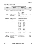
Page 41: ...4 mA Value in for output all others in engineering units 0 0 20mA VAL Auxiliary Output High Scaling Factor High scale value to represent 20 mA Value in for output all others in engineering units 0 DIG IN 1 Digital Input 1 Selections NONE MAN FS TO MAN ToLOCK TO LSP ToAout TO 2SP TIMER TO 3SP AM STA TO DIR ToTUNE ToHOLD SPinit ToPID2 TRACK1 PV 2IN TO RSP RERUN RST FB TO RUN ToPURG ToBEGN LoFIRE STO...

Page 42: ...unications Option State DISABL MODBUS MB3K RS422 DISABL Com ADDR Communications Station Address 1 to 99 0 SHEDENAB Shed Enable DISABL ENABL DISABL SHEDTIME Shed Time 0 to 255 sample periods 1 sample period 0 333 seconds 0 No Shed 0 PARITY Parity NONE ODD EVEN Fixed at NONE when ComSTATE MODBUS ODD BAUD Baud Rate 2400 4800 9600 19200 2400 DUPLEX Duplex Operation HALF FULL ATTENTION When ComSTATE MO...

Page 43: ...loating Point little endian FP LB Floating Point little endian with byte swapped TX DELAY Transmission Delay 1 to 500 milliseconds 1 SHEDMODE Shed Controller Mode and Output Level LAST TO MAN FSAFE ToAUTO LAST SHEDSP Shed Setpoint Recall TO LSP TO CSP TO LSP UNITS Communication Units PERCNT ENG PERCNT CSP RATO Loop 1 Computer Setpoint Ratio 20 0 to 20 0 1 0 CSP BIAS Loop 1 Computer Setpoint Bias 9...

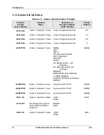
Page 44: ...2S2 VAL Alarm 2 Setpoint 2 Value Value in Engineering Units 5 A1S1TYPE Alarm 1 Setpoint 1 Type NONE INP 1 INP 2 PV Process Variable DEV Deviation OUTPUT SHED EV ON Event On SP Program EV OFF Event Off SP Program MANUAL REM SP Remote Setpoint F SAFE Failsafe PVRATE PV Rate of Change BREAK NONE A1S2TYPE Alarm 1 Setpoint 2 Type Same as A1S1TYPE NONE A2S1TYPE Alarm 2 Setpoint 1 Type Same as A1S1TYPE N...

Page 45: ...oint 1 State LOW HIGH HIGH A2S1 EV SP Programming Event Alarm State for Alarm 2 Setpoint 1 BEGIN END A2S2 H L Alarm 2 Setpoint 2 State LOW HIGH LOW A2S2 EV SP Programming Event Alarm State for Alarm 2 Setpoint 2 BEGIN END AL HYST Alarm Hysteresis 0 0 to 100 0 of output or span as appropriate 0 1 ALM OUT1 Latching Alarm for Output 1 NO LAT LATCH NO LAT BLOCK Alarm Blocking DISABL BLOCK1 BLOCK2 BLK ...

Page 46: ... 1 Temperature Units DEG F DEG C NONE NONE PWR FREQ Power Frequency 60 HZ 50 HZ 60 HZ RATIO 2 Ratio for Input 2 Set from the front of the controller DISABL ENABLE DISABL LANGUAGE Display Language ENGLIS FRENCH GERMAN SPANIS ITALAN ENGLIS 3 15 Calibration Group The prompts used here are for field calibration purposes Refer to Section 7 Calibration in manual 51 52 25 55 for complete information and ...

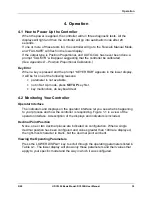
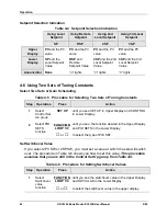
Page 47: ...ollowing reasons parameter is not available not in Set Up mode press SET UP key first key malfunction do keyboard test 4 2 Monitoring Your Controller Operator Interface The indicators and displays on the operator interface let you see what is happening to your process and how the controller is responding Figure 1 1 is a view of the operator interface A description of the displays and indicators is...

Page 48: ...Maximum negative display is 999 9 PIDSETX TUNING PARAMETER SET 1 Selected set for single loop or primary loop configuration where X is either 1 or 2 ET XX XX ELAPSED TIME Time that has elapsed on timer in Hours Minutes TR XX XX TIME REMAINING Time that remains on timer in Hours Minutes RAMPXXXM SETPOINT RAMP TIME Time remaining in the setpoint ramp in minutes O SK XXXX Soak and TIME REMAINING IN S...

Page 49: ...le memory INP1FAIL Two consecutive failures of input 1 integration INP2FAIL Two consecutive failures of input 2 integration SW FAIL Slidewire input failure Position proportional control automatically switched to TPSC CONF ERR Configuration Errors Low limit greater than high limit for PV SP Reset or Output SOOTING Input Combination Errors Percent Carbon falls outside of sooting boundary IN1 RNG Inp...

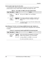
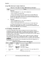
Page 50: ...ect automatic mode MANUAL AUTO until A indicator is ON The controller is in Automatic mode The controller will automatically adjust the output to maintain the process variable at setpoint if the controller is properly tuned 5 Tune the controller SET UP Tuning will be required on the first startup First enable TUNE selection in the Accutune Group Refer to Tuning Set Up group to ensure that the prop...

Page 51: ... and hold in the SETPOINT SELECT key Release when the desired active setpoint selection is displayed ATTENTION KEY ERROR will appear in the lower display if You choose either local setpoint 2 or 3 or remote setpoint and your choice has not been configured as the setpoint source You attempt to change the setpoint while a Setpoint Ramp is enabled Setpoint Ramp rate will apply to Local SP changes if ...

Page 52: ...ning Constants Step Operation Press Action 1 Select Control Set Up group SET UP until you see SET UP in Upper Display and CONTROL in Lower Display 2 FUNCTION LOOP 1 2 until you see the function desired in the Upper Display and PID SETS in the Lower Display Select PID SETS function or to select the type of PID SET Set Switchover Value If you select 2PV SW or 2SP SW you must set a value at which the...

Page 53: ...ilable constants in the Lower Display The value is displayed in the Upper Display 2 Select the tuning constants or To change the value of any of the above listed prompts in the lower display Switch Between Two Sets via the Keyboard Without Automatic Switchover This procedure is operational only if 2 PID SETS was configured at the Control Set Up group Table 4 8 Procedure for Switching PID SETS from...

Page 54: ... upper display 3 Return to normal operation LOWER DISPLAY 4 8 Three Position Step Control Algorithm The Three Position Step Control algorithm Loop 1 only allows the control of a valve or other actuator with an electric motor driven by two controller output relays one to move the motor upscale the other to move it downscale without a feedback slidewire linked to the motor shaft Accutune TUNE operat...

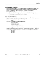
Page 55: ...as standard Weighted Average Feedforward Summer Feedforward Multiplier Input Algorithm Selections Algorithm selections are made in Section 3 Configuration The following function prompt can be found in the Algorithm Set Up group IN ALG1 This selection includes the following algorithms Weighted Average Feedforward Summer Feedforward Multiplier Carbon Potential several types Dewpoint Input A Input B ...

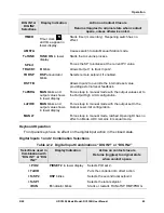
Page 56: ...blinks Puts the controller into local setpoint 2 TO 3SP RSP annunciator blinks Puts the controller into local setpoint 3 TO DIR Selects direct controller action ToHOLD H blinks Suspends setpoint program or setpoint ramp operation ToPID2 PIDSET2 in lower display Selects PID set 2 PV 2IN II II blinks IN Selects the PV to equal Input 2 RERUN Resets the Setpoint Program back to the beginning of the fi...

Page 57: ...display Forces loop to manual mode with the output values set to the Output High Limit configuration LoFIRE MAN blinks and output value shows in lower display Forces loop to manual mode with the output set to the Output Low Limit configuration MAN LT Forces loop to manual mode latched Opening DI has no effect on Mode UDC remains in manual mode Keyboard Operation Front panel keys have no effect on ...

Page 58: ...usly n by selecting prompt TUNE in the lower display n via digital input Configuration To configure this item refer to Section 3 Configuration Rules and Regulations TUNE On Demand tuning will work for all control algorithms except ON OFF Process line out is not required TUNE On Demand tuning works for integrating processes Tuning is done in automatic mode Tuning can be monitored or reconfigured us...

Page 59: ...o manual mode You can also disable TUNE in the ACCUTUNE Set Up group Tune for Duplex Heat Cool TUNE can be done for applications using duplex heat cool control During tuning Accutune requires that setpoint 1 will cause a Heating demand and then the calculated tuning parameters will be automatically entered as PID set 1 Likewise it requires that tuning at local setpoint 2 will cause a Cooling deman...

Page 60: ... PID set 2 in the Tuning group 4 13 Entering a Security Code The level of keyboard lockout may be changed in the Set Up mode However knowledge of a security code number 0 to 4095 may be required to change from one level of lockout to another When a controller leaves the factory it has a security code of 0 which permits changing from one lockout level to another without entering any other code numb...

Page 61: ...eration When a local setpoint change is made the controller will ramp from the original setpoint to the new one at the rate specified This changing current setpoint can be viewed as SPn on the lower display Press the LOWER DISPLAY key until you see SPn and the setpoint value in the lower display 5 2 Single Setpoint Ramp Introduction When you have configured a single setpoint ramp it will occur bet...

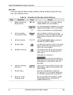
Page 62: ...et Start Setpoint or until the start setpoint value you desire is indicated in the lower display 4 Start the Ramp RUN HOLD You will see R and the PV value in the Upper Display and SP and the changing setpoint value in the Lower Display 5 Hold Run the Ramp RUN HOLD This holds the ramp at the current setpoint value SP can then be changed by the and keys Press again to continue run ATTENTION Any time...

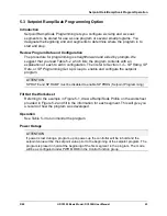
Page 63: ...ction 3 4 SP Ramp SP Rate or SP Programming Set Up Group to enable and configure the setpoint program ATTENTION SP RATE and SP RAMP must be disabled to enable SP PROG Setpoint Programming Fill Out the Worksheet Referring to the example in Figure 5 1 draw a Ramp Soak Profile on the worksheet provided in Figure 5 2 and fill in the information for each segment This will give you a record of how the p...

Page 64: ...d in TIME Hours Minutes Range 0 99hrs 59min Start Segment This designates the number of the first segment Odd number Range 1 to 11 End Segment This designates the number of the last Soak segment Even Number Range 2 to 12 Recycle Number This number allows the program to recycle to a specified number of times from beginning to end Range 0 to 99 Guaranteed Soak Each soak segment can have a deviation ...

Page 65: ... or PV is used as the setpoint when the program is initially changed from HOLD to RUN The selections are DISABL present LSP1 is default setpoint ENABL present PV value is used as beginning setpoint value for the ramp segment Reset Program to Beginning When enabled this selection allows you to reset the program to the beginning or rerun it from the keyboard ...

Page 66: ... TIME SEG6 SP Soak SP 6 250 RECYCLES Number of Recycles 2 SEG6TIME Soak Time 6 3hr 0min SOAK DEV Deviation Value 0 SEG7RAMP Ramp Time 7 2hr 30min PROG END Controller Status LAST SP SEG8 SP Soak SP 8 500 STATE Controller State at end HOLD SEG8TIME Soak Time 8 0hr 30min KEYRESET Reset SP Program DISABL SEG9RAMP Ramp Time 9 0 HOTSTART PV Hot Start Program Initialization or power up in SPP DISABL SG10...

Page 67: ...lue STRT SEG Start Seg SEG4TIME Soak Time 4 END SEG End Seg SEG5RAMP Ramp Time 5 RAMPUNIT Engr Unit for Ramp SEG6 SP Soak SP 6 RECYCLES Number of Recycles SEG6TIME Soak Time 6 SOAK DEV Deviation Value SEG7RAMP Ramp Time 7 PROG END Controller Status SEG8 SP Soak SP 8 STATE Controller State at end SEG8TIME Soak Time 8 KEYRESET Reset SP Program SEG9RAMP Ramp Time 9 HOTSTART PV Hot Start Program Initi...

Page 68: ...he HOLD state if the setpoint program is running The H in the upper display will blink indicating external hold is in effect Contact reopening runs program NOTE The keyboard takes priority over external switch for the RUN HOLD function Changing a Segment While in Hold or These keys will operate and allow you to change the segment number while in HOLD If a different segment is selected it will be s...

Page 69: ...nly Soak even only XX XX Ramp Time Hours Minutes Ramp Rate EU MIN or EU HR Soak Time Hours Minutes Viewing the Number of Cycles Left in the Program LOWER DISPLAY until you see Upper Display R and the PV value Lower Display RECYC XX Number of cycles remaining in the setpoint program XX 0 to 99 End Program When the final segment is completed the R in the upper display either changes to H if configur...

Page 70: ...Setpoint Rate Ramp Soak Program Operation 62 UDC3300 Basic Model DC330B User Manual 5 00 ...

Page 71: ...40 2 24 1 90 to 240 20 to 27 90 to 264 20 to 27 Frequency Hz For Vac 50 0 2 60 0 2 49 to 51 59 to 61 48 to 52 58 to 62 Power Consumption 18 VA maximum 90 to 264 Vac 12 VA maximum 24 Vac dc Input Accuracy 0 20 of span typical 1 digit for display Field calibratable to 0 05 of span typical 15 bit resolution typical CE Conformity Special Conditions Europe Shielded twisted pair cables are required for ...

Page 72: ...Environmental and Operating Conditions 64 UDC3300 Basic Model DC330B User Manual 5 00 ...

Page 73: ... Modbus Standard Functions includes Accutune II SPP Basic Model Digital Inputs 0 3 None Two Digital Inputs PV Input 1 2 3 1 6 Optional Input s 0 1 2 3 T C RTD Radiamatic mV 0 5V 1 5V T C RTD Radiamatic mV 0 5V 1 5V 0 20 mA 4 20 mA T C RTD Radiamatic mV 0 5V 1 5V 0 20 mA 4 20 mA 0 10V Carbon Oxygen or Dewpoint includes optional input None T C RTD Radiamatic mV 0 5V 1 5V 0 20 mA 4 20 mA Slidewire In...

Page 74: ...Model Selection Guide 66 UDC3300 Basic Model DC330B User Manual 5 00 ...

Page 75: ..._______ DISABL SP RATE _________ DISABL EU HR UP _________ 0 EU HR DN _________ 0 SP PROG _________ DISABL ACCUTUNE FUZZY _________ DISABL ACCUTUNE _________ DISABL AT ERROR Read Only Group Prompt Function Prompt Value or Selection Factory Setting ALGORTHM CONT ALG _________ PID A TIMER _________ DISABL PERIOD _________ 0 01 START _________ KEY L DISP _________ TI REM INP ALG1 _________ NONE MATH ...

Page 76: ... DIG IN 1 _________ NONE DIG1 COM _________ DISABL DIG IN 2 _________ NONE DIG2 COM _________ DISABL Group Prompt Function Prompt Value or Selection Factory Setting COM ComSTATE _________ DISABL Com ADDR _________ 0 SHEDENAB _________ DISABL SHEDTIME _________ 0 PARITY _________ ODD BAUD _________ 2400 DUPLEX _________ HALF WS FLOAT _________ PF b TX DELAY _________ 1 SHEDMODE _________ LAST SHED ...

Page 77: ... before you calibrate Leave all field wiring connected to the rear terminals There are two ways in which to calibrate Position Proportional or 3 Position Step control AUTO mode or MANUAL mode Rules for auto mode vs manual mode The Auto mode selection must be done at least once before the manual mode will operate properly Failure to use the Auto mode procedure will prevent the controller from going...

Page 78: ...ire has never been calibrated you must use DO AUTO first In the Automatic Calibration Mode DO AUTO the controller relays automatically move the motor in the proper direction If desired however the motor may be manually positioned to 0 and 100 positions Disconnect the relay wires Use DO MAN In the Manual Calibration Mode DO MAN the motor does not move Instead the existing 0 and 100 values may be ch...

Page 79: ...O VAL 9 or until the desired zero value is reached in the upper display Upper Display The desired zero value Lower Display ZERO VAL 10 DO MAN Set 100 value FUNCTION LOOP 1 2 The controller will store the 0 value and you will see Upper Display The existing span calibration value in counts Lower Display SPAN VAL 11 or until the desired span value is reached in the upper display Upper Display The des...

Page 80: ...Position Proportional Calibration 72 UDC3300 Basic Model DC330B User Manual 5 00 ...

Page 81: ...0 0 to 4200 0 to 2240 18 to 1816 270 to 1000 129 to 593 18 to 871 7 to 410 18 to 1316 29 to 538 0 to 1371 0 to 682 0 to 1371 0 to 682 18 to 1300 18 to 1704 18 to 1704 184 to 371 129 to 260 18 to 2315 18 to 1227 Honeywell Radiamatic Type RH Type RI 0 to 3400 0 to 9999 max 18 to 1871 18 to 9999 max RTD IEC Alpha 0 00385 100 ohms 100 ohms low 200 ohms 500 ohms 300 to 1200 300 to 300 300 to 1200 300 t...

Page 82: ...Input Ranges 74 UDC3300 Basic Model DC330B User Manual 5 00 ...

Page 83: ......

Page 84: ...Sensing and Control Honeywell 11 West Spring Street Freeport IL 61032 51 52 25 78 0500 Printed in USA www honeywell com sensing ...

Reviews: