background image

Honeywell BW Solo User Manual 


21 


7.


Navigation 

All navigation is done by pressing the single button on the Honeywell BW Solo. Here are the basic 

“rules” of navigation on the instrument: 


Power On 


3-second hold 

Power Off 


5-second hold from the main screen 


Enter menus (from main screen)


Double-click 

Move to next choice


Single-click (quickly press once) 

Select current choice 

Hold until acknowledged


Short Hold (press and hold for 1 second) 


Cursor or current choice stops blinking 


Cursor moves to next choice 

Hold through countdown


Long Hold (press and hold for 3 seconds) 


Selected process is initiated 


7.1.


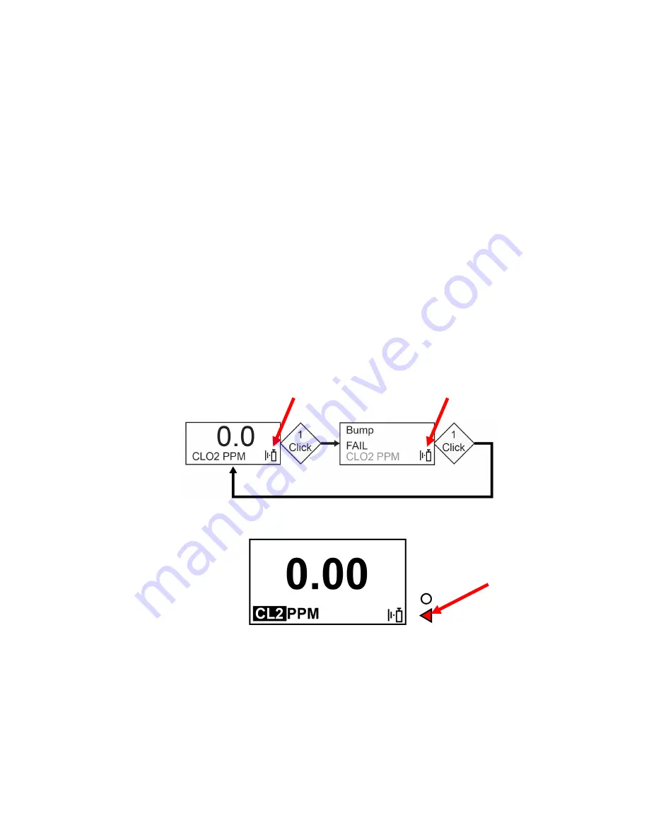
Glance Navigation 

At the main screen, press the button once, and the backlight comes on. In addition, a critically low 

battery level and any compliance issues are shown. For example, if the instrument fails a bump 

test, it will show a Bump FAIL. If there is a failure, an associated icon and fault message alert you.  


In addition, if there is a failure or low battery, the Alert LED will illuminate. 


Note: 

When the last screen is reached, if you click the button once, it returns to the main screen. If 

you do not click the button for 6 seconds from any of the screens, it returns to the main screen 

automatically. 


Bump Test 

icon blinks 

Bump Test 

icon blinks 

Alert LED 

Summary of Contents for BW Solo

Page 1: ...Honeywell BW Solo User Manual 1 Honeywell BWTM Solo User Manual Rev A October 2018 P N G05 4001 000 ...

Page 2: ...to a concentration of target gas that exceeds the low alarm set point A bump test is also recommended if the monitor has been subjected to physical impact liquid immersion an Over Limit alarm event or custody changes or anytime the monitor s performance is in doubt To ensure greatest accuracy and safety only bump test and calibrate in a fresh air environment The monitor should be calibrated every ...

Page 3: ...Turning The Honeywell BW Solo Off 19 6 3 Calibration Status 19 6 4 Bump Status 20 6 5 Sensor Fault Status 20 7 Navigation 21 7 1 Glance Navigation 21 7 2 Main Navigation 22 8 Navigation Information Menu 23 8 1 Event Log Navigation 24 9 Navigation Settings 25 9 1 Enter Settings Mode 25 9 2 Menus Submenus In Settings Mode 26 9 3 Language 27 9 4 Time 27 9 5 Date 27 9 6 Units 27 9 7 Readings 27 9 8 Se...

Page 4: ...ng The Sensor 37 13 4 1 4 Series Sensor Replacement 38 13 4 2 1 Series Sensor Replacement 40 13 5 Reinstalling The Cover 42 14 Maintenance 43 14 1 Cleaning 43 14 2 Replacing The Alligator Clip 43 14 3 Replacing Servicing Other Parts 43 15 Firmware Update 43 16 Year Of Manufacture 43 17 Sensors Settings 44 18 Troubleshooting 46 19 Honeywell BW Solo Specifications 47 20 Limited Warranty and Limitati...

Page 5: ...re Operating This manual must be carefully read by all individuals who have or will have the responsibility of using maintaining or servicing this product The product will perform as designed only if it is used maintained and serviced in accordance with the manufacturer s instructions The user should understand how to set the correct parameters and interpret the obtained results CAUTION To reduce ...

Page 6: ...e a gas concentration beyond the upper scale limit which can be hazardous Products may contain materials that are regulated for transportation under domestic and international dangerous goods regulations Return product in compliance with appropriate dangerous goods regulations Contact freight carrier for further instructions Recycling this instrument contains a lithium battery Do not mix with the ...

Page 7: ...ns However there is no guarantee that interference will not occur in a particular installation If this equipment does cause harmful interference to radio or television reception which can be determined by turning the equipment off and on the user is encouraged to try to correct the interference by one or more of the following measures Reorient or relocate the receiving antenna Increase the separat...

Page 8: ...OR SAFE USE WARNING Read and understand instruction manual before operation or servicing AVERTISSEMENT Lisez et comprenez le manual d instructions avant d utiliser ou d effectuer l entretien WARNING Substitution of components may impact safety AVERTISSEMENT La substitution de composants peut compromettre la sécurité WARNING Lithium battery Only use approved battery 2 3AA 3 6V 1 65Ah Lithium batter...

Page 9: ...oose alarm set points and more all from up to 6 meters away Also use the app to see calibration readings email calibration certificates and upgrade firmware With the Safety Communicator app detector readings are sent instantly to Honeywell s real time monitoring software Access it from any device with an internet connection and get remote visibility on worker safety and location You can also use t...

Page 10: ...g and programming functions The display is backlit when you press the button LED Visible Alarm Band Control Button Units Readings Audible Alarm Beeper Light sensor Alert LED Gas Inlets Filter Reference Window Sensor Cover Plate Display Sensor Type Status icons IR communication Port Alligator Clip Battery compartment Front Back ...

Page 11: ...ge screen is shown Step through the available languages by pressing the button Once you see the language you want press and hold the button for 1 second Note If you pass the language you want press the button until your language is shown Then press and hold the button for 1 second Once you have set the language wait 3 seconds and the Set time screen is shown Press and hold the button for 1 second ...

Page 12: ...mp test is required and indicated by this icon if The defined period between bump tests has been exceeded bump test overdue The sensor has failed a previous bump test Failed bump test notification is shown on the screen if a bump test is failed In the information menu it shows that the bump test must be performed NOW Note the sensor should be challenged on a regular basis before each day s use to ...

Page 13: ... license to transmit monitor alarm information from Honeywell Real Time Monitoring software 4 1 BLE Icons An icon is shown on the Honeywell BW Solo s screen to show the status of BLE Bluetooth Low Energy including connectivity Icon Explanation BLE connected The icon is shown when data is being transferred BLE is off BLE is on but is not connected 4 2 Non Compliance Indicator LEDs The non complianc...

Page 14: ...nstrument before attempting to pair it with smartphones or other iOS or Android devices 1 Open the Safety Communicator program 2 The app opens and begins scanning for nearby Bluetooth instruments As instruments are found they show up in the list If the Honeywell BW Solo does not show up click Scan so that it searches for the instrument ...

Page 15: ... its image and serial number 3 Click on the Honeywell BW Solo device that displays the serial number of the unit you are trying to connect This message appears 4 Look at the Honeywell BW Solo s screen and you will see a code number Input that code number into the field on your smartphone and then click Pair ...

Page 16: ...o User Manual 16 If it pairs successfully a confirmation message is shown If you want to pair another instrument click Pair another Otherwise click Done The Honeywell BW Solo is now sending data to Safety Communicator ...

Page 17: ...8 hours the icon blinks on and off every second and there are two beeps and a flash every 30 seconds Note To preserve the life of the battery deactivate the instrument when it is not in use 5 2 Battery Replacement WARNING To reduce the risk of ignition of hazardous atmospheres remove or replace the battery only in an area known to be non hazardous CAUTION Replace the battery in a safe area free of...

Page 18: ...on the instrument to make sure the battery was properly installed After a battery is inserted the screen shows a blinking battery icon The battery is being conditioned depassivation and it typically takes about 30 seconds If more time is required the blinking battery icon continues to be shown When depassivation is complete there is no battery icon on the screen The instrument can now be turned on...

Page 19: ...ing Down is shown Release the button When the instrument is off the screen is dark 6 3 Calibration Status Note When forced bump and calibration are enabled the instrument will power down if it is not bump tested or calibrated This icon is shown when less than 12 hours remains before a calibration should be performed The instrument beeps once every 10 30 60 seconds as set by the user when the user ...

Page 20: ...beeps three times every 60 seconds A bump test is required and indicated by this icon if The defined period between bump tests has been exceeded calibration overdue The sensor has failed a previous bump test Failed bump test notification is shown on the screen if a bump test is failed In the information menu it shows that the calibration must be performed NOW Note the sensor should be challenged o...

Page 21: ...Long Hold press and hold for 3 seconds Selected process is initiated 7 1 Glance Navigation At the main screen press the button once and the backlight comes on In addition a critically low battery level and any compliance issues are shown For example if the instrument fails a bump test it will show a Bump FAIL If there is a failure an associated icon and fault message alert you In addition if there...

Page 22: ...he button twice in rapid succession similar to a double mouse click to start 2 The first option you see is Information Step through the other top level options one click at a time Note A cursor before a heading indicates that there are submenus or editable parameters below the current screen ...

Page 23: ...nt Log which has its own navigation to show one or more events 1 Start at the main screen and click the button twice in rapid succession to start 2 When you see Information hold the button for 1 second 3 When the first screen Battery is shown you can progress through the screens by clicking the button once Note When you reach the Exit screen you can click once to cycle through the screens again or...

Page 24: ...event shown automatically in sequence from the date of the event to the start of the event to the conclusion of the event It also shows the reading and the type of alarm Low High etc When there are multiple events in the Event Log the screens cycle through a single event until you press the button Each time you press the button the next event is shown When all events have been shown the Exit promp...

Page 25: ...nter Settings Mode Note A passcode can be required to access the settings menu Setting an access restriction can be done using the Passcode submenu or by using an IntelliDoX with SafetySuite software To enter Settings from the main reading screen Press the button twice in rapid succession You should see Information Press the button again four times to reach Settings Press and hold the button for 1...

Page 26: ...ssed changed and saved in the same way 1 Press the button once to step from one setting to the next 2 When you find a setting to edit hold the button for 1 second The submenu for that setting is shown 3 Press the button once to step from one menu option to the next 4 When you find the option you want to select press and hold the button ...

Page 27: ...r 1 second to select it 9 5 Date The date can be shown in these formats the default is MM DD YYYY DD MM YYYY Day Month Year MM DD YYYY Month Day Year YYYY MM DD Year Month Day Single digits have a 0 prefix for example 01 02 etc When entering the year it loops in a range from 2018 to 2099 before returning to 2080 Press the button for 1 second to select each digit 9 6 Units The units of measure can ...

Page 28: ...e displayed When latching is on and mute is off and the instrument is in a safe atmosphere only the last gas alarm is displayed If the instrument is not in a hazardous atmosphere and you press the button to acknowledge the latching alarm shuts off Besides turning latching on and off you can turn the alarm mute on or off Note If latching the alarm is off the option to Mute is hidden in the menu cyc...

Page 29: ...11 Data Logging Turn datalogging on or off and set the frequency interval in seconds for data collection Note Turning data logging off hides the Interval setting option The default setting for Interval is 005 seconds and the interval can be set between 001 and 300 seconds The default setting for data logging is on 9 12 BLE On instruments that feature BLE Bluetooth Low Energy turn BLE communication...

Page 30: ... instrument at intervals you select This indicator notifies you that the monitor has no fault conditions and that all required maintenance such as bump test and calibration has been performed You can turn IntelliFlash on or off You can also turn the beep on or off and set the flash interval as 10 30 or 60 seconds The default setting for IntelliFlash is off The default interval is 30 seconds ...

Page 31: ...tinue to indicate a gas event by non compliance indication flash or flash and chirp 10 30 or 60 seconds 5 When a gas alarm is dismissed if latching alarm is turned on the instrument will continue to alert alarm behavior audible visible and vibration once per second After the button is pressed to acknowledge the latching alarm if Gas Event in non compliance settings is on the instrument will contin...

Page 32: ...Honeywell BW Solo User Manual 32 Exit to the main menu ...

Page 33: ...3 Press and hold the button down for 3 seconds The instrument counts down and then performs an AVV audible visible vibration alarm test You see Passed or Failed on the display 4 Press and hold the button to acknowledge the results You should see Apply Gas 5 Press the button to initiate the test IMPORTANT BUMP TEST THE MONITOR BEFORE EACH DAY S USE Prior to each day s use every gas detection monito...

Page 34: ...he button to initiate the bump test A progress bar indicates that the bump test is happening If the instrument passes the bump test the message Passed appears If the instrument fails the bump test the message Failed appears 10 When Turn Gas Off appears close the cylinder valve by turning the pressure regulator knob clockwise 11 Remove the calibration cap by pulling on the tab IMPORTANT If the sens...

Page 35: ...t says Zeroing It performs a zero calibration 6 When Apply Gas appears on the display open the cylinder valve by turning the pressure regulator knob counterclockwise 7 Start the calibration by pressing and holding the button for 1 second The calibration is indicated by a progress bar followed by Passed or Failed You can abort the calibration by clicking the button once IMPORTANT If it fails calibr...

Page 36: ... the holes in the sensor cover has a clear plastic window While the other holes allow ambient air and dirt debris etc to reach the filter the window keeps the part of the filter under it clean As a result it is easy to visually confirm that the filter needs replacement by simply comparing the clean spot with the other spots 13 2 Removing The Cover Remove the front cover by using the tab end of the...

Page 37: ...ESD wrist or heel strap when replacing the sensor Avoid touching electronic components on the detector printed circuit board or shorting circuits on the printed circuit board 4 Use only the sensor specifically designed for the Honeywell BW Solo Otherwise the detector will not monitor the target gas 5 Ensure that the sensor cover is properly aligned to ensure a proper environmental seal 6 After rep...

Page 38: ...he O ring 1 Series or sealing ring 4 Series Series for reuse it when installing the replacement sensor 13 4 1 4 Series Sensor Replacement IMPORTANT Some 4 Series sensors are shipped with a jumper that connects two of the pins This jumper must be removed before installing the sensor Turn the sensor upside down and slide the spring tensioned jumper off of the sensor s pins Properly dispose of the ju...

Page 39: ...Honeywell BW Solo User Manual 39 ...

Page 40: ...e in place Note Do not overtighten Install a new filter over the sensor before replacing the cover 13 4 2 1 Series Sensor Replacement IMPORTANT Some Series 1 sensors are shipped with a jumper that connects two of the pins This jumper must be removed before installing the sensor Turn the sensor upside down and slide the jumper off of the sensor s pins Properly dispose of the jumper Sealing Ring Sen...

Page 41: ... sensor and stretch the O ring around the perimeter of the sensor Invert the sensor and press the sensor all the way until it is fully seated in the sensor frame Insert the sensor assembly into the instrument Tighten the screws to secure the assembly in place Do not overtighten the screws Install a new filter over the sensor before replacing the cover 1 Series Sensor Rear View Notch Sensor Frame P...

Page 42: ...ver the compartment press upper part into place first and then press the lower part until it clicks IMPORTANT Always calibrate the instrument after you replace the sensor Failure to calibrate the instrument can result in inaccurate readings Some sensors require conditioning time before first use ...

Page 43: ... infrared IR sensor on the rear of the instrument is clean to ensure best communication quality 14 2 Replacing The Alligator Clip If the alligator clip is damaged or loose replace the combined alligator clip battery door together 14 3 Replacing Servicing Other Parts Many interior components including the display vibration alarm and horn gasket are replaceable but service should only be performed b...

Page 44: ... ppm CO H 0 2000 ppm 0 5 ppm 30 to 50 C 22 to 122 F 35 ppm 200 ppm NH3 0 100 1 ppm 20 to 40 C 4 to 104 F 25 ppm 50 ppm NH3 extended range 0 400 1 ppm 20 to 40 C 4 to 104 F 25 ppm 50 ppm SO2 0 100 ppm 0 1 ppm 30 to 50 C 22 to 122 F 2 ppm 5 ppm HCN 0 100 ppm 0 1 ppm 20 to 50 C 4 to 122 F 4 7 ppm 10 ppm Cl2 0 50 ppm 0 1 ppm 20 to 40 C 4 to 104 F 0 5 ppm 1 0 ppm NO 0 250 ppm 0 2 ppm 30 to 50 C 22 to 1...

Page 45: ...0 to 40 C 4 to 104 F 25 ppm 50 ppm NH3 extended range 0 400 1 ppm 20 to 40 C 4 to 104 F 25 ppm 50 ppm SO2 0 100 ppm 0 1 ppm 30 to 50 C 22 to 122 F 2 ppm 5 ppm HCN 0 100 ppm 0 1 ppm 20 to 50 C 4 to 122 F 4 7 ppm 10 ppm Cl2 0 50 ppm 0 1 ppm 20 to 40 C 4 to 104 F 0 5 ppm 1 0 ppm NO 0 250 ppm 0 2 ppm 30 to 50 C 22 to 122 F 25 ppm 25 ppm NO2 0 100 ppm 0 1 ppm 20 to 50 C 4 to 122 F 2 ppm 5 ppm PH3 0 5 p...

Page 46: ...ot display a normal ambient gas reading after the activation self test Target gas is present Detector is operating properly Use caution in suspect areas Detector requires calibration Calibrate the detector Sensor not stabilized Used sensor Wait 60 seconds New sensor wait 5 minutes The detector does not respond to the pushbutton Battery is depleted Replace the battery Detector is performing operati...

Page 47: ... hold Sampling Diffusion Calibration Automatic with IntelliDoX or manual Alarms Multi tone audible 95 dB 30 cm 12 vibration visible flashing bright red LEDs and on screen indication of alarm conditions Real time remote alarm notification Wireless Model Only Datalogging Continuous datalogging six months at 5 second intervals running continuously User configurable datalogging interval 1 to 300 secon...

Page 48: ...8 Ex ia IIC T4 Ga Ex ia I Ma Tamb 40 C to 60 C FCC ID SU38WS1 IC 20969 BWS1 RED RE D Directive 2014 53 EU For additional certifications consult Honeywell Analytics CE Compliance European Conformity EMC directive 2014 30 EU RE directive 2014 53 EU ATEX directive 2014 34 EU FCC Compliance FCC Part 15 Languages Chinese Dutch English French German Italian Japanese Korean Portuguese Russian Spanish War...

Page 49: ...g or use any damage or defects attributable to repair of the product by any person other than an authorized dealer or the installation of unapproved parts on the product The obligations set forth in this warranty are conditional on proper storage installation calibration use maintenance and compliance with the product manual instructions and any other applicable recommendations of Honeywell Analyt...

Reviews: