background image

Bump Test via DC

Apply gas from a cylinder to the sensors manually through the calibration cap, and using the
Device Configurator (DC) app on a mobile device.

1. Turn On the BW Flex Series. Wait a few minutes to sensors warm up.
2. In your mobile device, open the Detector Configurator app, and pair with the detector. For

details, go to See "Bluetooth Pairing" on page


13 for more information.

3. In your mobile device, tap on the Menu button and then select Bump Test.
4. Enter the Operator Name, and then Tap Save. The IntelliFlash LED flashes amber to indicate

the bump test process has started.

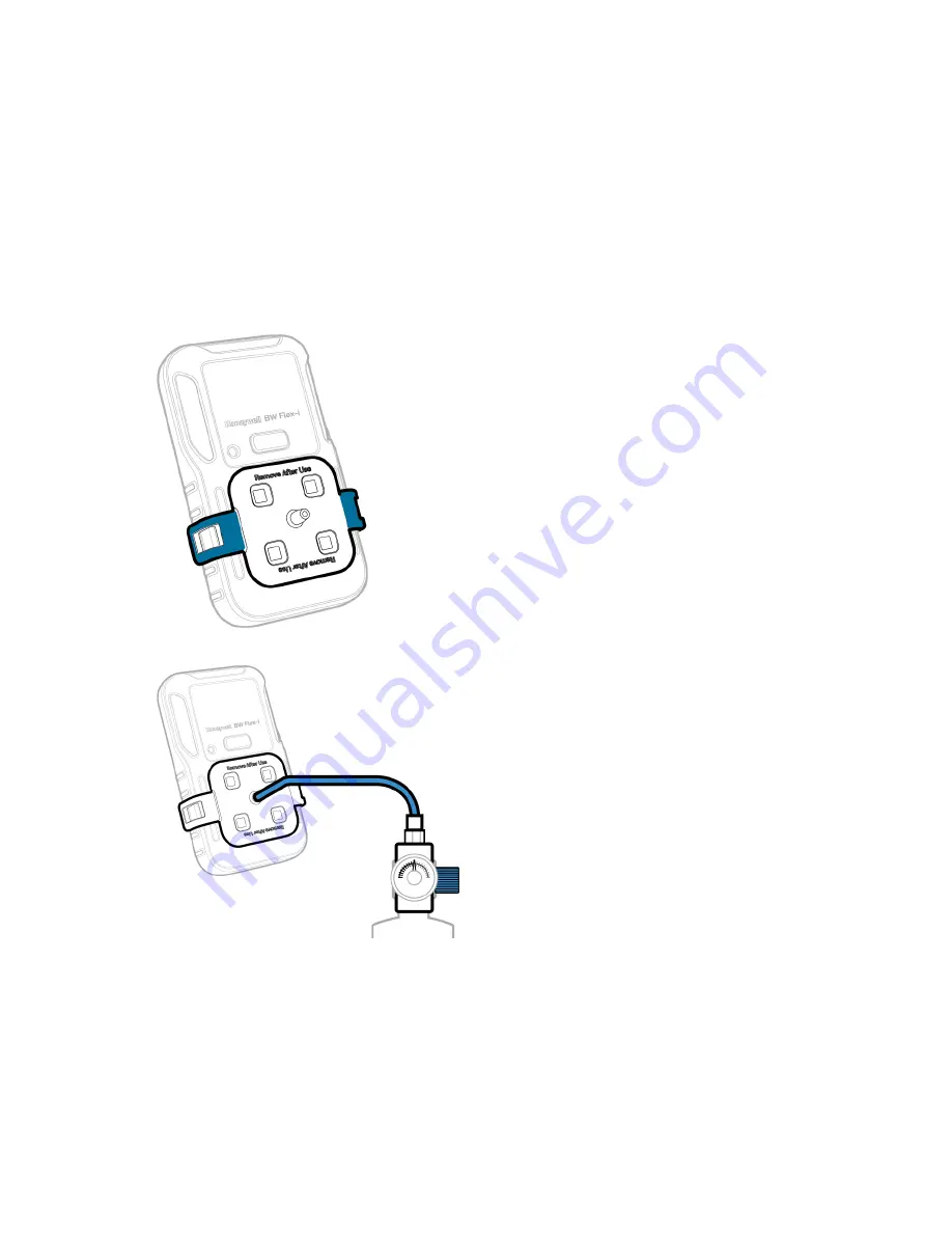
5. Place the cap over the detector, and then press down on both tabs to snap it into place. Wait

a few minutes to sensors warm up.

6. Attach the hose.

BW Flex Series

28

User Manual

Summary of Contents for BW Flex Series

Page 1: ...USER MANUAL Honeywell BW Flex Series Portable Multiple Gas Detector M05 4002 003 EN Rev A ...

Page 2: ......

Page 3: ...1 Self Test 11 Deactivate the Detector 12 Common Button Operations 12 Bluetooth Pairing 13 Calibration 14 Bump Test 23 Force Calibration and Bump 30 Zero Calibration 30 Capture Real Time Reading 30 Configure the detector Settings via DC 31 Maintenance 33 Clean the Detector 33 Charge the Battery 33 Update Firmware 36 Replace the Belt Clip or Klick Fast Stud 37 Replace the Sensor Filter 38 Replace a...

Page 4: ...g 44 DataLogs and Event Logs 46 Alarms 47 Combustible Sensor Information 49 Filtered and Unfiltered Catalytic Bead Combustible LEL Sensor Information 50 User Preferences 53 Replacement Parts 56 Accessories 57 Security Information 58 Contact Us 60 BW Flex Series 3 User Manual Additional Information 41 ...

Page 5: ...etector l Use only Honeywell approved battery chargers such as the vehicle Charger l Do not use the Detector if it is damaged Inspect the Detector before use Look for cracks and missing parts l Honeywell recommends bumping test the sensors before each day s use to confirm their ability to respond to gas by exposing the detector to a gas concentration that exceeds the alarm setpoints Manually verif...

Page 6: ...r installed Ex ia op is I Ma Ex ia op is IIC T4 Ga 40 C Tamb 60 C With LEL sensor installed Ex da ia I Ma Ex da ia IIC T4 Ga 40 C Tamb 60 C With IR and LEL sensor installed Ex da ia op is I Ma Ex da ia op is IIC T4 Ga 40 C Tamb 60 C Without IR and LEL sensor installed Ex ia I Ma Ex ia IIC T4 Ga 40 C Tamb 60 C ATEX Sira 20ATEX2012X With IR sensor installed I M1 Ex ia op is I Ma 40 C Tamb 60 C II 1G...

Page 7: ...ding interference that may cause undesired operation Note This equipment has been tested and found to comply with the limits for a Class A digital Detector pursuant to part 15 of the FCC Rules These limits are designed to provide reasonable protection against harmful interference when the equipment is operated in a commercial environment This equipment generates uses and can radiate radio frequenc...

Page 8: ... installed 1 USB charger 1 Calibration cap 1 Klick Fast stud 1 Quick Reference Guide 1 Tubing Overview 1 Alarm LED 6 Sensor 2 IntelliFlash 7 Clip 3 Display 8 Certification model and Serial Number 4 Button 9 Charging and IR connection Port 5 Beeper BW Flex Series 7 User Manual ...

Page 9: ... connected l BLE fault l IR connected l Profile mode l AVV failed l Stealth mode l Sensor fault l Sensor EOL l Cal fail due l Cal countdown l Predictive Cal due l Bump fail due l Bump countdown l Inert Mode l Press and hold the button l Wait l Warning l Pass l Fail l Back l Next l Information l Bump l Zero l Calibration l Exit BW Flex Series 8 User Manual ...

Page 10: ...fteen seconds and the detector goes to the Regular mode You are now ready to select any operation from the main menu Note We strongly recommend to review the Alarm Settings after Start Up Set Language Time and Date Configure the Language time and Date in a new detector on the first run setup There are four ways to set the Time Zone and Language in a new detector l Manual configuration via onscreen...

Page 11: ...oth Pairing on page 13 for more information 3 After pairing the Quick Setup window requests to Continue or Cancel Tap OK to continue 4 Choose Language and Time Zone and then tap Save to complete the setup Configure the detector via SSDC on a computer Configure the detector via the Safety Suite Device Configurator SSDC software You can download SSDC from https explore honeywell com safety_suite_dev...

Page 12: ... the Sensor warm up the sensors LEDs flash clockwise In the regular mode the IntelliFlash flashes green every fifteen seconds Self Test When the detector is activated it performs several start up tests Firmware Version BLE Version End Of Life sensors if any Bump Due Date by sensor Calibration Due Date by sensor Low Alarm Setpoint by sensor High Alarm Setpoint by sensor STEL Alarm Setpoint by senso...

Page 13: ...tor To deactivate your Honeywell BW Flex Series detector press the button and hold for four seconds The detector beeps and vibrates and the alarm LEDs light red Common Button Operations Feature Operation Power On 4 second hold Power Off 4 second hold Enter the menu Double Press Exit the menu on Exit screen Press and hold Move to Next Option menu Single Press Initiate Selected Option 3 second hold ...

Page 14: ... readings and alarms from the BW Flex Series unit that is connected and then send this data to the Honeywell remote monitoring software On the Honeywell BW Flex Series the Bluetooth connection is on by default 1 Turn On the BW Flex Series detector and your mobile device 2 In your mobile device activate the Bluetooth and open the Device Configurator app 3 Select the detector s serial number in the ...

Page 15: ...in the LEL range calibrate the sensor using the appropriate gas l The IR combustible sensor will be calibrated to 50 LEL methane and must only be calibrated with methane See Combustible Sensor Information on page 49 for more information for approximate response to other target gases Guidelines When calibrating the detector adhere to the following guidelines l Recommended gas mixture CO 100 ppm bal...

Page 16: ...librate the detector during or immediately after charging is complete l The oxygen sensor can be automatically calibrated each time upon activation if this feature is enabled Activate the detector in a normal 20 9 20 8 oxygen atmosphere l Allow the detector to stabilize for 1 minute after activation before performing a calibration or bump test l If a certified calibration is required contact Honey...

Page 17: ... Zero Calibration is complete place the cap over the detector and press it down on both tabs to snap it into place 5 Attach the hose 6 Follow on screen instructions Note If sensors fail to detect the gas or cannot be spanned repeat the calibration If the problem persists replace the sensor 7 Remove the calibration cap the detector starts purging and the slots LEDs flash amber clockwise After the p...

Page 18: ...e information 3 In your mobile device tap on the Menu button and then select Remote Calibration 4 Tap Calibration the IntelliFlash flashes amber to indicate the calibration process has started Note If sensors fail to detect the gas or cannot be spanned repeat the calibration If the problem persists replace the sensor 5 Enter the Operator Name and then Tap START The detector will start Zero Calibra...

Page 19: ...Scanning Scan the bar code from the cylinder Selecting Choose the Last Time User cylinder information Typing Manual input of the gas concentration BW Flex Series 18 User Manual 6 After the Zero calibration is completed place the cap over the detector and then press down on both tabs to snap it into place ...

Page 20: ...nt to calibrate and then tap START 10 Open the cylinder valve by turning the pressure regulator knob counterclockwise Follow onscreen instructions to know when to apply gas The IntelliFlash lights amber BW Flex Series 19 User Manual ...

Page 21: ... to exit the report and go back to the remote calibration main screen The detector will start purge and the slots LEDs will flash amber clockwise After purge is completed the detector will go to the regular mode 12 Remove the hose and the calibration cap BW Flex Series 20 User Manual ...

Page 22: ...her information refer to the SSDC User Manual 4 Click on the Device View tab the SSDC scans for connected devices or you can click Refresh to browse manually 5 Select the connected detector and then click Start Bump Cal 6 In the Start Bump Calibration Test window do the following l Select Calibration l Select the sensor You can modify the default values l Click START TEST l Wait for several second...

Page 23: ... Span calibration is completed the LEDs are solid green if calibration passed or red if failed Note If sensors fail to detect the gas or cannot be spanned repeat the calibration If the problem persists replace the sensor 8 Remove the calibration cap The detector starts purging and the slots LEDs flash in amber clockwise After the purge is complete the Detector is back to the regular mode BW Flex S...

Page 24: ...ump testing the sensors before each day s use to confirm their ability to respond to gas by exposing the Detector to a gas concentration that exceeds the alarm setpoints Manually verify that the audible and visual alarms activate Details for Bump Test and maintenance l Recommendations for initial checking of the equipment on a routine basis including the maximum time interval between calibrations ...

Page 25: ...over the detector and then press down on both tabs to snap it into place 5 Attach the hose 6 Apply span gas when the sensor slot LEDs start flashing The bump test starts after the BW Flex Series detects gas The four slots LEDs flash blue clockwise After the bump test is completed the LEDs are solid green if calibration passed or red if failed 7 Remove the calibration cap the detector starts purgin...

Page 26: ...o sensors warm up 2 Connect the detector to the PC via the IR link 3 Log in to SSDC with an authorized user account For further information refer to the SSDC User Manual 4 Click the Device View tab the SSDC scans for connected devices or you can click Refresh to browse manually 5 Select the connected detector and then click Start Bump Cal 6 In the Start Bump Calibration Test window do the followin...

Page 27: ...LEDs flash blue clockwise After the bump test is completed the LEDs are solid green if calibration passed or red if failed Note If sensors fail to detect the gas or cannot be spanned repeat the bump test If the problem persists replace the sensor 10 Remove the calibration cap The detector starts purging and the slots LEDs flash in amber clockwise After the purge is complete the Detector is back to...

Page 28: ...process starts and a message is displayed when succeeded 14 Follow onscreen instructions to know when to apply gas and when the bump test process is complete Note If sensors fail to detect the gas or cannot be spanned repeat the bump test If the problem persists replace the sensor 15 The process is complete when the results are displayed on your mobile device You can now remove the cap by pulling ...

Page 29: ...r app and pair with the detector For details go to See Bluetooth Pairing on page 13 for more information 3 In your mobile device tap on the Menu button and then select Bump Test 4 Enter the Operator Name and then Tap Save The IntelliFlash LED flashes amber to indicate the bump test process has started 5 Place the cap over the detector and then press down on both tabs to snap it into place Wait a f...

Page 30: ...ap by pulling on the tabs BW Flex Series 29 User Manual 7 In the Input Gas level screen check the sensor that you want to test and enter the Span gas concentration and then tap START 8 Open the cylinder valve by turning the pressure regulator knob counterclockwise The Zero process starts and a message is displayed when succeeded 9 Follow onscreen instructions to know when to apply gas and when the...

Page 31: ...displayed press and hold the button and within 60s you can enter to the flow of cal bump Zero Calibration Over time and through use the sensor baseline at zero exposure may drift from the manufacturer s baseline For optimal performance Honeywell recommends that you zero the sensors periodically Only zero calibrate the sensor in fresh air 1 Double press the button to enter the menu 2 Single press t...

Page 32: ... Flex Series with the Device Configurator App on your mobile device 2 Tap the menu button 3 Tap Detector Setup 4 Tap Download to get the configuration table 5 Tap Edit to change the settings and then tap Upload to apply them BW Flex Series 31 User Manual ...

Page 33: ......

Page 34: ...ve the life of the battery deactivate the Detector when not in use The battery operating temperature is 40 C to 60 C WARNING The Honeywell BW Flex Series uses a Li ion battery that may present a risk of fire or chemical burn hazard if misused Do not disassemble heat above 100 C or incinerate CAUTION l To avoid personal injury and property damage adhere to the following l Charge the battery immedia...

Page 35: ... bar battery icon The Inteliflash flashes green 5h 12h Normal Static 1 bar battery icon The Inteliflash flashes green 5h 12h Battery low Static empty battery icon Display exclamation mark instead of SAFE The IntelliFlash flashes amber 1h Battery critical Flash empty battery icon The IntelliFlash flashes amber the Alarm LEDs flashes red alternatively The detector beeps and vibrates 20min Battery Ic...

Page 36: ... detector is ON Charge the battery via the Cradle Charger 1 Deactivate the detector 2 Insert the detector into the detector bay and press down firmly on the detector to ensure contact between the detector and the contact pins The detector can be activated during charging 3 After charge is complete the full battery icon is displayed 4 Remove the detector Note For further information refer to the Cr...

Page 37: ... 5 Tap YES to start the Firmware update and wait until the Update Successfully system message is displayed The detector goes to the Regular mode Update Firmware via SSDC 1 Connect the detector to Safety Suite Device Configurator via IR Link or Bluetooth 2 Select the detector in the Device List to enter the configuration page 3 Safety Suite Device Configurator checks new firmware automatically afte...

Page 38: ...ly Replace the Belt Clip or Klick Fast Stud If the belt clip or Klick Fast Stud is damaged or loose replace it with a new one Insert a screwdriver through the hole in the clamp and loosen the screw to detach the clip Put a new clip or Klick Fast Stud in place and fasten it BW Flex Series 37 User Manual ...

Page 39: ...sensors inserted in the front enclosure 3 Remove the sensor filter from the inside of the front enclosure 4 Place a new filter in place 5 Reassemble the detector in the reverse order Compress front enclosure and back enclosure Use the screwdriver vertically to fasten the four screws with 3kgf cm torque first and then use 5kgf cm torque to fasten the four screws again BW Flex Series 38 User Manual ...

Page 40: ...le the detector in the reverse order Compress front enclosure and back enclosure Use the screwdriver vertically to fasten the four screws with 3kgf cm torque first and then use 5kgf cm torque to fasten the four screws again CAUTION Improper re assembly of the BW Flex series detector could lead to damage and loss of ingress protection An improper paste of the filter could lead to loss of ingress pr...

Page 41: ......

Page 42: ...ectants Bug repellents and sprays Lubricants Silicone based adhesives sealants and gels Lubricants Rust inhibitors Hand body and medicinal creams that contain silicone Rust inhibitors Window and glass cleaners Tissues containing silicone Window and glass cleaners Dish soaps Mold releasing agents Citrus based cleaners Polishes Alcohol based cleaners Hand sanitizers Anionic detergents Methanol fuels...

Page 43: ...d from 40 C to 20 C Sensor SPAN Count Down Default SPAN Value Calibration Flow Rate New Sensor Stabilization Time CO 60 sec 100ppm 500ml min 0 5 hour H2S 60 sec 25ppm 500ml min 0 5 hour SO2 90 sec 20ppm 500ml min 0 5 hour O2 60 sec 18 0 v v 500ml min 24 hours LEL IR 60 sec 50 LEL CH4 500ml min N A LEL 60 sec 50 LEL 500ml min N A Sensor Default Low Alarm Default High Alarm Default TWA Default STEL ...

Page 44: ...SO2 Combustible gases Display Monochrome 160X80px black and white display Alarms Condition Low Alarm High Alarm TWA Alarm STEL Alarm Negative Drift Over Range Alarm Multi Alarm Visual Alarm 6 Main Alarm LED s and 4 sensor LEDs Audible Alarm 95 dBA at 10cm Battery Life 40 days 8 hour per day at room temperature with Catalytic Combustible sensor 16 hours at room temperature with the LEL sensor Event...

Page 45: ...orce Calibration Cal Now message is displayed Calibration overdue and must carry out calibration testing before use Hold the button for 3 seconds or connect to DC SSDC or insert to IntelliDoX to start the Calibration otherwise the detector will auto power off after 60 secs Detector alarms after start up sequence Sensor not stabilized O2 sensor Wait for at least 10 min before power on Sensors requi...

Page 46: ...a communication via a mobile phone Detector is in IR communication Stop data communication via IR Link The Detector alarms without reason Thesensor was exposed to the target gas Detector is operating normally Use caution in suspected areas Check the peak gas exposure reading Alarm setpoints are set incorrectly Define the alarm setpoint in Detector Configurator Sensors require calibration Carry out...

Page 47: ...full the detector replaces the oldest datalogs with the most recent datalogs Event Logs The detector records a maximum of 50 gas alarm maintenance events and error conditions The following event types are recorded 1 Gas high 2 Gas low 3 Gas STEL 4 Gas TWA 5 Gas over range 6 Gas negative 7 Sensor failure 8 Multi alarm 9 Zeroing 10 Spanning 11 Bumping 12 Disabled BW Flex Series 46 User Manual ...

Page 48: ...at kind of gas alarms they are Alarm type from high priority to low Description Multi Alarm MULTI ALARM message is displayed Alarm LEDs alternately flash Alarmed sensor LEDs flash too It beeps and vibrates Over Limit OL message is displayed Alarm LEDs alternately flash Alarmed sensor LED flashes too It beeps and vibrates High HIGH message is displayed Alarm LEDs alternately flash Alarmed sensor LE...

Page 49: ...brates TWA TWA message is displayed Alarm LEDs alternately flash Alarmed sensor LED flashes too It beeps and vibrates Low LOW message is displayed Alarm LEDs alternately flash Alarmed sensor LED flashes too It beeps and vibrates Negative OL message is displayed Intelliflash LED flashes amber Alarmed sensor LED turns solid red BW Flex Series 48 User Manual ...

Page 50: ...Catalytic LEL sensors Identifying Combustible Sensor Type The type of combustible sensor may be determined by the model number printed on the Certification serial number label on the rear of the device as shown in the following example The model number should look like CPD W6X1H1M1 Y 00 the type of combustible sensor is identified by the 4th and 5th characters in this case W6 Use the following tab...

Page 51: ...d and Unfiltered Catalytic Bead Combustible LEL Sensor Information Honeywell BW Flex multi gas detectors are offered with both filtered and unfiltered combustible gas LEL sensors The filtered LEL sensor provides enhanced resistance to airborne sensor poisons such as volatile silicone vapors and high hydrogen sulfide gas concentrations Due to some molecules physical size the filtered LEL sensor is ...

Page 52: ...10 X X n Pentane C5H12 X X n Hexane C6H14 X X n Heptane C7H16 X n Octane C8H18 X n Nonane C9H20 X Methanol CH3OH X Ethanol C2H6O X Iso propyl alcohol C3H8O X Acetylene C2H2 X X 1 3 Butadiene C4H6 X X Carbon monoxide CO X X Acetone C3H6O X Methyl ethyl ketone C4H8O X Toluene C7H8 X Ethyl acetate C4H8O2 X Ammonia NH3 X X Cyclohexane C6H12 X X BW Flex Series 51 User Manual ...

Page 53: ...ecommended for detection of combustible gases with flash points greater than 37 8 C 100 F Correction Factor for catalytic type combustible LEL sensors The following table shows the relative sensitivity of several common detectable gases based on a methane CH4 calibration This table applies to both Filtered and Unfiltered versions of the catalytic combustible sensors offered in the BW Flex detector...

Page 54: ...nce If enabled the blanking zone will be disabled and the minus reading will be display Disabled is the default value l Low Alarm Acknowledge If enabled the audible alarm can be disabled during a Low Alarm The vibration visual indication and LCD remain enabled It applies for H2S CO and LEL sensors only l Cal Bump Countdown This countdown is an indication before calibration due Users can customize ...

Page 55: ...ata to reduce Synchronization Time Enabled is the default value l Lockout on Self Test Error If enabled and a failure occurs during the self test the detector deactivates Disabled is the default value l TWA amp STEL Backup If enabled when the device is powered down for greater than 2 hours then STEL TWA calculations will start freshly Disabled is the default value l Latching Alarms If enabled the ...

Page 56: ...en after the alarm condition is cleared To acknowledge a latched alarm press the button l Time zone Specify the time zone where the detector is used l Automatically Adjust Clock for Daylight Savings Time Determine whether to use daylight saving time l Spring Start Time For daylight saving time specify the date and time when the spring starts l Fall End Time For daylight saving time specify the dat...

Page 57: ...ensor CP BC1 Back shell Yellow CP BC1B Back shell Black CP VM 1 Vibration motor CP BAT Battery pack CP KF Klickfast stud CP SF2 LCD and Sensor frame CP SS Sensor Membrane kit of 4 CP SS K1 Sensor membrane kit of 20 CP AG Alligator Clip CP SS AF K1 Filters 10pcs CP SCREW K1 Housing screws 20pcs CP LCD K1 LCD Kit CP FC3 Front enclosure BW Flex i CP FC4 Front enclosure BW Flex4 CP LBL 3 Sensor label ...

Page 58: ...P AF K3 External Filter Kit GA PA 1 MC5 Mains 5 way charger CP USB USB Charger 5 8V 1A DX NEST CP IntelliDox nest DX CP IntelliDox CP C01 5 5 way cradle charger CP TC 1 Calibration cap BW Flex Series 57 User Manual ...

Page 59: ...ireless connectivity l Bluetooth communication is always ON It cannot be turned OFF by the user l If possible pair devices ONLY when in a physically secure area System Monitoring It is highly recommended to perform regular security inspections of the system and review authorized access data Honeywell does not represent that the software is compatible with any specific third party hardware or softw...

Page 60: ...tal special or consequential however arising as a result of accessing or using the software So long as this provision is enforceable in Customer s jurisdiction the foregoing limitations exclusions and disclaimers apply to the fullest extent permitted by law even if any remedy fails of its essential purpose BW Flex Series 59 User Manual ...

Page 61: ... pricing or further information please contact us using the details below Cadmus Products Tel 44 0 330 088 0595 Email info cadmus co uk Website www cadmus co uk Please note Product designs and specifications are subject to change without notice The user is responsible for determining the suitability of this product ...

Reviews: