Honeywell ADEMCO Optiflex Installation And Setup Manual Download Page 23


LIMITED WARRANTY 

Honeywell International Inc., acting through its Security & Custom Electronics business ("Seller") 165 
Eileen Way, Syosset, New York 11791, warrants its product(s) to be in conformance with its own plans 
and specifications and to be free from defects in materials and workmanship under normal use and 
service for 24 months from the date stamp control on the product(s) or, for product(s) not having a 
manufacturer’s date stamp, for 12 months from date of original purchase unless the installation 
instructions or catalog sets forth a shorter period, in which case the shorter period shall apply. Seller's 
obligation shall be limited to repairing or replacing, at its option, free of charge for materials or labor, 
any product(s) which is proved not in compliance with Seller's specifications or proves defective in 
materials or workmanship under normal use and service. Seller shall have no obligation under this 
Limited Warranty or otherwise if the product(s) is altered or improperly repaired or serviced by anyone 
other than Honeywell factory service. Connection of any device(s) to a communicating bus of a Honeywell 
security system (e.g., keypad bus, polling loop) other than those manufactured or approved by Honeywell 
shall void this warranty.  For warranty service, return product(s) transportation prepaid, to Honeywell 
Factory Service, 165 Eileen Way, Syosset, New York 11791. 

THERE ARE NO WARRANTIES, EXPRESS OR IMPLIED, OF MERCHANTABILITY, OR FITNESS 
FOR A PARTICULAR PURPOSE OR OTHERWISE, WHICH EXTEND BEYOND THE DESCRIPTION 
ON THE FACE HEREOF. IN NO CASE SHALL SELLER BE LIABLE TO ANYONE FOR ANY 
CONSEQUENTIAL OR INCIDENTAL DAMAGES FOR BREACH OF THIS OR ANY OTHER 
WARRANTY, EXPRESS OR IMPLIED, OR UPON ANY OTHER BASIS OF LIABILITY 
WHATSOEVER, EVEN IF THE LOSS OR DAMAGE IS CAUSED BY THE SELLER'S OWN 
NEGLIGENCE OR FAULT. 

Seller does not represent that the product(s) it sells may not be compromised or circumvented; that the 
product(s) will prevent any personal injury or property loss by burglary, robbery, fire or otherwise; or 
that the product(s) will in all cases provide adequate warning or protection. Customer understands that 
a properly installed and maintained alarm system may only reduce the risk of a burglary, robbery, fire

,


or other events occurring without providing an alarm, but it is not insurance or a guarantee that such 
will not occur or that there will be no personal injury or property loss as a result. CONSEQUENTLY, 
SELLER SHALL HAVE NO LIABILITY FOR ANY PERSONAL INJURY, PROPERTY DAMAGE OR 
OTHER LOSS BASED ON A CLAIM THAT THE PRODUCT(S) FAILED TO GIVE WARNING. 
HOWEVER, IF SELLER IS


HELD LIABLE, WHETHER DIRECTLY OR INDIRECTLY, FOR ANY 

LOSS OR DAMAGE ARISING UNDER THIS LIMITED WARRANTY OR OTHERWISE, REGARDLESS 
OF CAUSE OR ORIGIN, SELLER'S MAXIMUM LIABILITY SHALL NOT IN ANY CASE EXCEED 
THE PURCHASE PRICE OF THE PRODUCT(S), WHICH SHALL BE THE COMPLETE AND 
EXCLUSIVE REMEDY AGAINST SELLER. 

This warranty replaces any previous warranties and is the only warranty made by Seller on this 
product(s). No increase or alteration, written or verbal, of the obligations of this Limited Warranty is 
authorized.


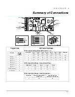
Summary of Contents for ADEMCO Optiflex

Page 1: ... e e e e ex x x x x x x x V V V V V V V Vi i i i i i i id d d d d d d de e e e e e e eo o o o o o o o C C C C C C C Co o o o o o o on n n n n n n nt t t t t t t tr r r r r r r ro o o o o o o ol l l l l l l ll l l l l l l le e e e e e e er r r r r r r r Installation and Setup Guide Installation and Setup Guide Installation and Setup Guide Installation and Setup Guide K0948V2 11 04 Rev A ...

Page 2: ......

Page 3: ...3 NTSC Output Configuration 2 5 NTSC Guard Tour Mode Camera Scanning Mode Camera Dwell Time 2 5 NTSC Guard Tour Mode Camera Selection 2 5 Section 3 Setting Up Optiflex Using Symphony 3 1 How to Enable Video on Symphony 3 1 How to Set Up Video Options on Symphony 3 2 Section 4 Operational Status Indicators 4 1 Camera Status LEDs 4 1 Network Status LEDs 4 1 Optiflex Status LEDs 4 2 Camera Status 4 2...

Page 4: ......

Page 5: ...rt for up to six camera inputs One Monitor Output Integral 4204 Relay Module capability Selectable Dwell Time for Guard Tour Viewing sequential scanning of multiple cameras Time and Date Stamping Camera Identification Local and or remote viewing capabilities Video captures up to 19 captures of 10 frames each viewable through Optiflex Connect remote viewing or Optiflex Direct local viewing on PC Se...

Page 6: ...gh an Ethernet hub router to a PC or Symphony for remote viewing programmed in the control panel to be triggered by selected events of the security system and viewed locally on a Symphony connected to the security system control panel used as a standalone system with only a monitor or a Symphony for local viewing configured for all of the above Figure 1 Optiflex System Block Diagram Showing Possib...

Page 7: ...re turned on using Output relay Programming commands in the control panel To accomplish this enable a 4204 Relay Module in the system s Device Programming Mode as Device Address 12 Then program eight logical relays and point to the same four physical relays twice programmed as shown in the table below using system events or zones zone lists as desired to turn on the relays as shown below Cameras a...

Page 8: ... into the two tabs located at the bottom of Optiflex with the blade of a screwdriver while pulling the case back and case front apart 2 Locate the case back over the mounting surface such that the opening in the case back is aligned with the wire cable access opening in the mounting surface while passing the wires cable through the opening in the case back 3 Secure the case back to the mounting su...

Page 9: ...to be disabled In non UL installations requiring ground fault detection when possible use cameras powered by a power source such as a plug in transformer that is not earth grounded and isolate the camera s mounting brackets from earth ground Connect a video ground loop isolation device such as Vicon s V235GLTA Ground Loop Transformer to the coaxial cable that runs between Optiflex and the video mo...

Page 10: ...header position 4 Data In terminal of Optiflex yellow wire UL Use a Listed cable DSL router suited for the application 3 If using remote viewing over Ethernet connect the LAN cable Category 5 between the Optiflex Ethernet connector and the hub router LAN connector 4 Connect a cable Category 5 from the camera to one of the Optiflex camera connectors Up to six cameras can be connected one to each po...

Page 11: ...h Use All Six Cameras for Guard Tour Use First Four Cameras for Guard Tour 6 OFF ON 8 Turn on the power source Wait approximately 30 seconds while the Optiflex software loads and the video sources are detected During this time Optiflex scans for cameras and if they are detected begins monitoring them If they are not detected they will not be monitored During the boot up process the cover should be...

Page 12: ...iflex Installation and Setup Guide 2 6 Optiflex can be reset to its default settings by pressing and holding the top reset button for 10 seconds The system will automatically reboot to the default settings ...

Page 13: ...ly buttons whose options are functional in the system should be displayed To enable video do the following 1 Press the SECURITY button on the Home screen The Arming screen is displayed 2 Press the MORE CHOICES button The More Choices screen is displayed 3 Press the SETUP button on the More Choices screen The Setup screen is displayed 4 Press the ADVANCED SETUP button The Enter Authorized Code auth...

Page 14: ... your 4 digit Installer code The Advanced Setup menu screen is displayed 6 Press the Video Setup button The Video Setup screen is displayed 7 Edit Camera 1 name and label and position Save the data Repeat this for each camera 8 Select default camera for local viewing on Symphony 9 Select NTSC default camera for NTSC composite monitor viewing In order to enable remote viewing over the Internet usin...

Page 15: ...ost Network Status LEDs LINK ON when Ethernet link is detected and OFF when Ethernet link is not detected SELECT Flashing indicates Ethernet Controller activity RX Flashing indicates data being received over the Ethernet connection TX Flashing indicates data being transmitted over the Ethernet connection optiflex 007 V0 23456 1 ON 78 LEDs ETHERNET STATUS LIGHTS CAMERA STATUS LEDs ...

Page 16: ...ras are connected Flashing At least one camera lost Camera Activity On At least one camera is detected Off No cameras detected Flashing At least one camera is being viewed Power On power applied to Optiflex Off No power applied to Optiflex optiflex 006 V0 CAMERA STATUS CAMERA ACTIVITY POWER NOT USED ...

Page 17: ...n Video Storage Local Refresh Rate Compression Technology NTSC Six RJ45 connectors Single camera 320 x 240 Quad Display 160 x 120 Flash Memory 19 captures of up to 10 frames each oldest images are deleted when buffer is full Four frames second for single camera viewing Quad view approximately one frame second JPEG NETWORK WAN LAN Interface 10 Base T Ethernet TRIGGERS Event Driven Video Capture Eig...

Page 18: ...Optiflex Installation and Setup Guide 5 2 ...

Page 19: ...SC Output Configuration DIP Switch 1 3 Dip Switch Cam 1 View Cam 2 View Cam 3 View Cam 4 View Cam 5 View Cam 6 View Guard Tour Reserved 1 OFF ON OFF ON OFF ON ON OFF 2 OFF OFF ON ON OFF OFF ON ON 3 OFF OFF OFF OFF ON ON ON ON NTSC Guard Tour Mode Camera Dwell Time Dip Switch 2 sec 4 sec 8 sec 16 sec 4 OFF ON OFF ON 5 OFF OFF ON ON Function Voltage Trigger 12VDC Camera 1 1 Camera 2 2 Camera 3 3 Cam...

Page 20: ...Optiflex Installation and Setup Guide 6 2 ...

Page 21: ...NOTES ...

Page 22: ...NOTES ...

Page 23: ... A PARTICULAR PURPOSE OR OTHERWISE WHICH EXTEND BEYOND THE DESCRIPTION ON THE FACE HEREOF IN NO CASE SHALL SELLER BE LIABLE TO ANYONE FOR ANY CONSEQUENTIAL OR INCIDENTAL DAMAGES FOR BREACH OF THIS OR ANY OTHER WARRANTY EXPRESS OR IMPLIED OR UPON ANY OTHER BASIS OF LIABILITY WHATSOEVER EVEN IF THE LOSS OR DAMAGE IS CAUSED BY THE SELLER S OWN NEGLIGENCE OR FAULT Seller does not represent that the pr...

Page 24: ...165 Eileen Way Syosset NY 11791 Copyright 2004 Honeywell International Inc www honeywell com security ÊK0948V2pŠ ÊK0948V2pŠ ÊK0948V2pŠ ÊK0948V2pŠ K0948V2 11 04 Rev A ...

Reviews: