

¬19Ul
N9080-1V2 3/04
multiple speaker systems, cutting any speaker will trip the
control panel’s supervision zone. In parallel-connected
speaker systems, each branch must be cut before the control
panel’s supervision zone will trip. Note: The Supervision
option has been determined to be compatible with the
controls listed in Table 2.
2 B/F: BURGLARY/FIRE INPUT:
Connect the control panel’s Burglary (steady) Output to this
terminal. This terminal may also be used to trip the FIRE
message if the control provides a pulsing output for fire (re-
programming may be required). In this case, no connection
to terminal 3 is required.
3F: FIRE INPUT:
Connect the control panel’s output designation as the FIRE
(steady) Output to this terminal (unless this output was
connected to terminal 2).
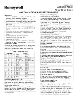
4 SPKR & 5 SPKR: SPEAKER TERMINALS:
Connect an 8-ohm, 16-ohm, or 32-ohm 15-watt speaker to
these terminals. See Figure 3 for multiple speaker
configurations. For UL installations, the Listed Ademco
705-820, 713, or 746-32 speakers must be used.
6(+): 12VDC(+) POWER INPUT:
Connect to a 12VDC (+) source on the control.
7(-): GND(-) GROUND INPUT:
Connect to a ground point (-) on the control panel.
Speakers Specifications
: Use compatible speakers above.
Sound Output: 85 dB minimum @10 ft.
Current Drain (max):
8-ohm Speaker: 1400 mA (steady siren)
12-ohm Speaker: 1050 mA (steady siren)
16-ohm Speaker: 875 mA (steady siren)
32-ohm Speaker: 500 mA (steady siren)
Important
:
The 745x3 must be mounted in the control
cabinet.
745x3-001-V0
SPEAKER
8
SEE
TABLE
1
JP2
JP3
JP6
JP7
JP4
JP5
JP1
BURG & FIRE
INPUT SIGNAL
INTACT = HIGH
CUT = LOW
FIRE
BURG
SPEAKER SUPERVISION
CONNECT TO (+) SIDE OF
24 - HR ZONE ON CONTROL.*
TO BURGLARY/FIRE ALARM
OUTPUT ON CONTROL.**
TO FIRE ALARM
OUTPUT ON CONTROL
*IF EOLR SUPERVISION DESIRED ON THIS ZONE,
USE APPROPRIATE EOLR IN ACCORDANCE WITH
THE CONTROL'S INSTRUCTIONS.
**IF THE ALARM OUTPUT IS
STEADY
FOR BURG AND
PULSING
FOR FIRE, NO CONNECTION IS NEEDED AT TERMINAL 3.
4
3
6
5
7
2
1
12VDC
GND
VOICE
SIREN
DRIVER
Figure 1. Siren Driver Board
745x3-002-V0
VOICE
SIREN
DRIVER
7( )
6( )
CONTROL
GROUND
12V ( )
POS
( )
NEG
( )
2 AMP
IN-LINE FUSE
BATT
Figure 2. Connecting Power from the System’s Battery
(Not applicable for UL installations)
745x3-003-V0
2 SPEAKERS
16 OHM
LOAD
4 SPEAKERS
8 OHM LOAD
3 SPEAKERS
12 OHM
LOAD
8
8
8
8
8
8
8
8
8
5
4
5
4
5
4
Figure 3. Typical Multiple Speaker Configurations
Table 2. Wiring Connections For Honeywell Ademco
Control Panels*
REFER TO THE INSTALLATION INSTRUCTIONS FOR THE
CONTROL PANEL THAT IS USED WITH THIS DEVICE FOR
WARRANTY INFORMATION AND LIMITATIONS OF THE
ENTIRE ALARM SYSTEM.
165 Eileen Way, Syosset, New York 11791
Copyright © 2004 Honeywell International, Inc.
www.honeywell.com/security
745x3 TERMINALS
ADEMCO
CONTROL
PANEL
1 2
3
4
5
6
7
4110
4110XM
VISTA-10P/15P/20P
VISTA-10SE/20SE
3
–
Splice to Red BATT
lead thru 2A fuse
(see Fig. 2).
For UL
Installations, use
the 32-ohm speaker
(746-32) and
connect to +12V
LUG
4
4140XM 8
–
+12V
LUG
15
4140XMP
4140XMPT
VISTA-40/
VISTA-50P
VISTA-128B/BP
OPTION
AL S
P
KR
S
U
PERVIS
ION
(C
ON
N
ECT T
O
2
4
-H
R
Z
O
N
E
)
4 –
S
P
EAKER CO
N
N
E
CTION
S
Splice to RED
BATT lead thru 2A
fuse
(see Fig. 2).
For UL
Installations, use
the 32-ohm speaker
(746-32) and
connect to +12V
LUG.
5
* For further information, consult the control panel’s instructions.
Note:
If using the 745x3 with a control with a built-in siren
driver, consult that control’s instructions to determine the method
to disable the built-in siren driver and enable the bell output.