


Page 2 of 4
SET THE DIP SWITCHES
Use the DIP switches to set the 5883H’s device address, to enable
the built-in transmitter, and to check or delete encrypted keys.
Addresses:
The 5883H Transceiver has two device addresses: one
for the receiver (addresses 1-7) and one for the transmitter
(addresses 27-30, similar to the 5800TM device addresses; see
notes 5 and 6 below). First, select a pair of addresses from the table
below, making sure that neither address is currently being used in
the alarm system, then use DIP switches 2-4 to set the address
pair. The addresses should then be programmed in the control. Do
not program the transmitter’s address in the control if the 5883H
is not being used with 5800TM compatible devices.
DIP Switch Functions
Sw. Function
1
Check/deactivate high-security keys (see High-Security Keys paragraph)
Device Address Settings
Transmitter:
28 29 30 27 28 29 30
Receiver:
Non-
Addr.*
1 2 3 4 5 6 7
2
OFF OFF OFF OFF ON ON ON ON
3
OFF OFF ON ON OFF OFF ON ON
4
OFF ON OFF ON OFF ON OFF ON
5
Reserved - must be OFF
6
ON = enable transmitter (if using 5800TM compatible devices)
NOTE: If using more than one 5883H in a system, enable the
transmitter in only one 5883H.
OFF = disable transmitter
7
Not used; leave in OFF position
8
Used when removing RF keypads (see Removing RF Keypads
paragraph); otherwise leave OFF
•
also address “0.” See VISTA-15P/20P note at right.
NOTES:
•
DIP switches 2–4 select both an RF receiver and an RF
transmitter device address.
•
When used with 5800TM compatible (bi-directional) devices, the
transmitter address must be enabled as a “keypad” in the control
and DIP switch 6 must be set to “ON.”
•
If 5883H is not being used with 5800TM compatible devices, the
RF transmitter address should be ignored and DIP switch 6
should be set to OFF.
•
If programming the control to supervise 5883H, program only
the receiver address for supervision. Do not program the
transmitter address for supervision.
•
5883H does not support the 5827BD Wireless Keypad.
Special Notes When Used With Certain Controls
VISTA-40:
When using bi-directional devices, use device address
setting 1/28 or 5/28 for devices used in partition 1; use device
address setting 2/29 or 6/29 for devices used in partition 2 (this
is necessary because the VISTA-40 automatically assigns
address 28 or 29 depending on the programming in field 1*48,
wireless keypad partition assignment).
VISTA 32FB, VISTA-50P and higher:
When using bi-
directional devices, the Wireless Keypad Partition Assignment
field (typically 1*48) must be set to the partition in which the
devices are used (cannot be used on Fire Partitions).
VISTA-15P/20P Series, FA130C/FA148C/FA168CP Series:
Use device address setting of “non-addressable,” which is
address 0 (sets the receiver address; the transmitter address (for
bi-directional devices) is automatically set for 28).
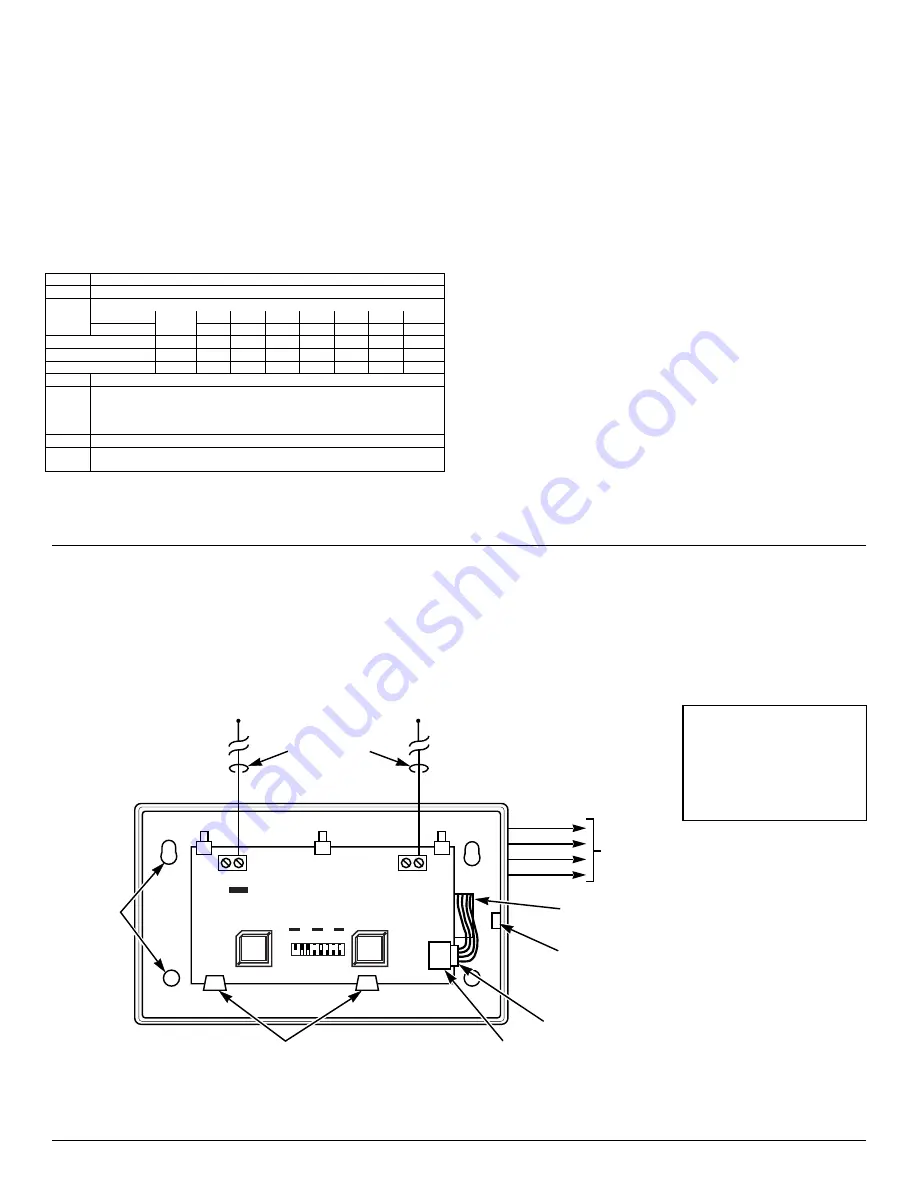
CONNECT THE WIRING FROM THE CONTROL
1. Insert the wiring plug (with 5 flying leads) into the mating
socket on the 5883H (see Figure 5 for socket location).
2. Connect the 4 wires to the control's corresponding remote
keypad connection points as follows:
RED
12VDC input (+) Aux Power
GREEN:
Data to Control (control’s data IN)
YELLOW:
Data from Control (control’s data OUT)
BLACK:
Ground
(–)
LED FUNCTIONS
(refer to Figure 5)
Red RF Interference LED: Lit Indicates local RF interference.
Green LED: Flickering indicates reception of messages (decoded
and/or non-decoded).
Yellow LED: Occasional blinks occur under normal operation.
Red LED: Blinks indicate available space for high security keys;
Steady ON indicates ready to deactivate high security keys or
remove wireless (RF) keypads. See High Security Keys and
Wireless Keypads section.
RF INTERFERENCE
RED INDICATOR
RED
YEL
GRN
DIP SWITCH
ON
OFF
2 3 4 5 6 7 8
1
5883 CIRCUIT BOARD
MOUNTING
HOLES
(4)
ANTENNAS
(INSERT IN
RIGHT-HAND
TERMINALS)
YELLOW
RED
BLACK
GREEN
WIRING
OPENING
KNOCKOUT AREA
FOR SURFACE WIRING
TO
CONTROL'S
REMOTE
KEYPAD
CONNECTION
POINTS
TO RELEASE CIRCUIT BOARD,
BEND BACK TABS
SOCKET
PLUG
5883-002-V0
Figure 5. 5883H RF Transceiver
IMPORTANT: Take precautions
against static discharge when
handling the 5883 PCB. A static
discharge can damage the
module’s EEPROM and/or cause
unpredictable changes in its
factory programming.