

Akku
MP
+
-
U_ext.
Mains
230 V AC
Si3 0.63 AT
Si2 1.25 AT
Si1 0.25 AT
4k7
0 V
U_b
Mains
Fault
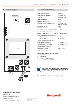
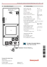
5.
Connection diagram
6.
Technical data
Adjustment of the accumulator
charging voltage
(see functional description)
Resistor for adjusting the
accumulator charging voltage
Layout of fuses Si1 to Si4:
Si1: Mains fuse
Si2: Accumulator charging
Si3: Ext. user 12 V DC
Si4: Secondary fuse - transformer
Rated operating voltage
230 V AC
Operating voltage range
-15 % to +10 %
Frequency
40 Hz to 60 Hz
Power consumption
22 VA
Maximum constant current
0.5 A
Short-term drain of current (5 min.)
0.8 A max.
Accum. charging voltage
13.8 V
Maximum charging current
0.13 A
As per VdS approved accu. capacity
7.2 Ah max.
No. of connectable accumulators
1
Possible accum. combinations e.g. 1x1.2 Ah to 1x6.5 Ah
Current consumption as per VdS at 7.2 Ah
- for 12 hours
approx. 500 mA
- for 60 hours
approx. 120 mA
Permanent accum. monitoring
Operating temperature range
-5 °C to +45 °C
Storage temperature range
-25 °C to +70 °C
Environmental class as per VdS
II
PCB dimensions:
60 x 140 mm
see maximum constant current
1)
1)
(with
charged accum.)
PO 1
Si4 1.6 AT
TR1
If the power unit is operated without an
accumulator, an electrolytic capacitor of
100 µF must be connected.
³
4 Mounting and Connection Instructions Mains/charger unit 12 V DC / 7.2 Ah
2012-04-20
© 2012 Novar GmbH
P00201-10-002-07
Honeywell Security Group
Novar GmbH
Johannes-Mauthe-Straße 14
D-72458 Albstadt
www.honeywell.com/security/de