background image

8-6

dummyhead

dummyhead

IGNITION SYSTEM

WB20XT2•WB30XT2

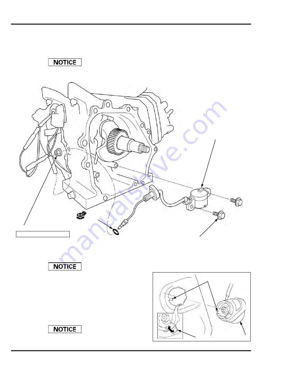
OIL LEVEL SWITCH 
REMOVAL/INSTALLATION

Disconnect the 

Oil Alert

 unit connector.

Remove the camshaft (page 13-4).

Take care not to drop the valve lifter.

ENGINE STOP SWITCH 
REMOVAL/INSTALLATION

Remove the engine stop switch only if necessary for
engine stop switch or fan cover replacement.

Remove the fan cover (page 5-2).
Straighten the tab (1) of the engine stop switch (2) and

remove the engine stop switch.
Install the engine stop switch to the fan cover, aligning

its groove with the boss of the fan cover.
Bend the tab until it is fully seated on the fan cover so

the engine stop switch is held.

The tab is used for ground terminal.

Install the fan cover (page 5-2).

OIL LEVEL SWITCH

BOLT (6 x 12 mm) (2)

O-RING

NUT (10 mm)

10 N·m (1.0 kgf·m, 7 lbf·ft)

(2)

(1)

Align

Summary of Contents for WB20XT2

Page 1: ...ing appropriate clothing and using safety equipment When performing any service task be especially careful of the following Read all of the instructions before you begin and make sure you have the too...

Page 2: ...0 5 dummyhead dummyhead OUTLINE OF CHANGES Item Before modification After modification Pump WB20XT3 Pump WB30XT3 OUTLINE OF CHANGES...

Page 3: ...ONS 1 SERVICE INFORMATION 2 MAINTENANCE 3 TROUBLESHOOTING 4 COVER 5 FUEL SYSTEM 6 GOVERNOR SYSTEM 7 IGNITION SYSTEM 8 STARTING SYSTEM 9 PUMP 10 ENGINE REMOVAL INSTALLATION 11 CYLINDER HEAD 12 CRANKCAS...

Page 4: ...t is not practical or possible to warn you about all the hazards associated with servicing these products You must use your own good judgement Honda Motor Co Ltd SERVICE PUBLICATION OFFICE Date of Iss...

Page 5: ...hole Use only metric tools when servicing this unit Metric bolts nuts and screws are not interchangeable with non metric fasteners The use of incorrect tools and fasteners will damage the unit SYMBOLS...

Page 6: ...R Digital Auto Voltage Regulator EBT Engine Block Temperature ECT Engine Coolant Temperature ECM Engine Control Module EMT Exhaust Manifold Temperature EOP Engine Oil Pressure EX Exhaust F Front or Fo...

Page 7: ...1 1 1 dummytext 1 SPECIFICATIONS SERIAL NUMBER LOCATION 1 2 SPECIFICATIONS 1 2 PERFORMANCE CURVES 1 4 DIMENSIONAL DRAWINGS 1 5...

Page 8: ...numbers when ordering parts and when making technical inquiries SPECIFICATIONS DIMENSIONS AND WEIGHTS FRAME SERIAL NUMBER ENGINE SERIAL NUMBER Model WB20XT2 WB30XT2 Description code WABT WACT Type A...

Page 9: ...uretor Horizontal type butterfly valve Air cleaner Semi dry type Governor Mechanical centrifugal Breather system Reed valve type Fuel tank capacity 2 0 liters 0 53 US gal 0 44 Imp gal 3 1 liters 0 82...

Page 10: ...liter 19 oz 0 49 Imp qt 0 58 liter 19 5 oz 0 51 Imp qt Recommended oil SAE 10W 30 API service classification SJ or later Cooling system Forced air Starting system Recoil starter Stopping system Ignit...

Page 11: ...B30XT2 PERFORMANCE CURVES WB20XT2 WB30XT2 0 20 40 60 80 100 120 0 20 40 60 80 100 120 140 160 Discharge Capacity gallons per minute Total Head feet 0 20 40 60 80 100 120 0 50 100 150 200 250 300 Disch...

Page 12: ...200 300 400 500 liters min 35 600 700 50 0 100 0 US gal min DISCHARGE CAPACITY 150 0 200 0 TOTAL HEAD LIFT 20 40 60 80 100 120 feet 5 10 15 20 25 m 200 400 600 800 1000 liters min 1200 TOTAL HEAD LIFT...

Page 13: ...1 5 dummyhead dummyhead WB20XT2 WB30XT2 SPECIFICATIONS DIMENSIONAL DRAWINGS Unit mm in 455 17 9 WB20XT2 510 20 1 WB30XT2 420 16 5 WB20XT2 455 17 9 WB30XT2 365 14 4 WB20XT2 385 15 2 WB30XT2...

Page 14: ...1 4 dummyhead dummyhead DIMENSIONAL DRAWINGS Unit mm in 490 19 3 WB20XT3 510 20 1 WB30XT3 420 16 5 WB20XT3 455 17 9 WB30XT3 365 14 4 WB20XT3 385 15 2 WB30XT3...

Page 15: ...MEMO dummyhead dummyhead...

Page 16: ...2 1 2 dummytext 2 SERVICE INFORMATION MAINTENANCE STANDARDS 2 2 TORQUE VALUES 2 4 LUBRICATION SEAL POINTS 2 5 TOOLS 2 6 HARNESS AND TUBE ROUTING 2 8...

Page 17: ...e 0 1 0 4 0 004 0 016 1 1 0 04 Big end I D 26 020 26 033 1 0244 1 0249 26 066 1 026 Big end oil clearance 0 040 0 063 0 0016 0 0025 0 12 0 005 Crankshaft Crankpin O D 25 970 25 980 1 0224 1 0228 25 92...

Page 18: ...e 0 1 0 4 0 004 0 016 1 1 0 04 Big end I D 30 020 30 033 1 1819 1 1824 30 066 1 1837 Big end oil clearance 0 040 0 063 0 0016 0 0025 0 12 0 005 Crankshaft Crankpin O D 29 970 29 980 1 1799 1 1803 29 9...

Page 19: ...switch joint nut M10 x 1 25 10 1 0 7 Flywheel nut M14 x 1 5 Special nut 75 7 6 55 Fuel tank nut bolt M6 x 1 0 10 1 0 7 Fuel tank joint M10 x 1 25 2 0 2 1 5 Air cleaner elbow nut M6 x 1 0 9 0 9 6 6 Ai...

Page 20: ...vernor weight holder sliding surface and gear Governor holder shaft journal Governor arm shaft journal Flywheel nut threads and seating surface Cylinder head bolt threads and seating surface Oil seal...

Page 21: ...uge 07401 0010000 Valve guide driver 5 5 mm 07742 0010100 Driver 07749 0010000 Attachment 37 x 40 mm 07746 0010200 Attachment 52 x 55 mm 07746 0010400 Pilot 25 mm 07746 0040600 Pilot 22 mm 07746 00410...

Page 22: ...rder by phone call 1 888 424 6857 Customer service representatives are available from 7 30 AM until 7 00 PM CT Monday through Friday Tool name Tool number Application Fuel line clip pliers HCP6A Carbu...

Page 23: ...2 HARNESS AND TUBE ROUTING CARBURETOR INSULATOR WB20XT2 HIGH TENSION CORD HIGH TENSION CORD WB30XT2 CARBURETOR INSULATOR ENGINE WIRE HARNESS IGNITION COIL CONNECTOR CORD HOOK ENGINE WIRE HARNESS CYLIN...

Page 24: ...2 9 dummyhead dummyhead WB20XT2 WB30XT2 SERVICE INFORMATION FUEL TUBE BREATHER TUBE HIGH TENSION CORD WB20XT2 WB30XT2 CARBURETOR INSULATOR FAN COVER CLAMP CARBURETOR INSULATOR...

Page 25: ...CONNECTOR ENGINE STOP SWITCH WIRE ENGINE WIRE HARNESS CLAMP WB30XT2 To ignition coil To Oil Alert unit To oil level switch To engine stop switch OIL ALERT UNIT WIRES Bl Y Bl Y Y Bl OIL LEVEL SWITCH CO...

Page 26: ...SPARK PLUG CHECK ADJUSTMENT 3 5 SPARK PLUG REPLACEMENT 3 5 SEDIMENT CUP CLEANING 3 6 IDLE SPEED CHECK ADJUSTMENT 3 6 VALVE CLEARANCE CHECK ADJUSTMENT 3 7 COMBUSTION CHAMBER CLEANING 3 9 FUEL TANK AND...

Page 27: ...ch use First month or 20 hrs Every 3 months or 50 hrs Every 6 months or 100 hrs Every year or 300 hrs Engine oil Check Level 3 3 Change 3 3 Air cleaner Check 3 4 Clean 1 3 4 Spark plug Check Adjust 3...

Page 28: ...ing center or service station for reclamation Do not throw it in the trash pour it on the ground or pour it down a drain Install the drain plug bolt with a new drain plug washer and tighten it to the...

Page 29: ...ter securely Remove the following Wing nut 1 Air cleaner cap 2 Air cleaner cover 3 Air cleaner element 4 If the element is dirty clean it page 3 4 Carefully check the element for holes or tears and re...

Page 30: ...plug cap 1 and remove the spark plug 2 Clean around the spark plug base with compressed air before removing the spark plug and be sure that no debris is allowed to enter into the combustion chamber IN...

Page 31: ...art of the sediment cup for any sign of fuel leakage IDLE SPEED CHECK ADJUSTMENT Ensure the governor arm and governor arm shaft are installed correctly page 7 4 Use a tachometer with graduations of 50...

Page 32: ...top dead center of the cylinder compression stroke both valves fully closed by pulling the recoil starter slowly When the piston is near top dead center of the compression stroke the triangle mark 1...

Page 33: ...ot and retighten the lock nut to the specified torque Recheck the valve clearance and if necessary readjust the clearance Replace the head cover packing with a new one and install the removed parts in...

Page 34: ...ith non flammable solvent and allow them to dry thoroughly Check the screen of the fuel tank joint for clogs or damage replace if necessary Install a new O ring to the fuel tank joint and install them...

Page 35: ...ecking WB30XT2 remove the fan cover page 5 2 IMPELLER CHECK Remove the impeller cover 1 page 10 5 Check the impeller 2 for damage or contamination and replace if necessary Gasoline is highly flammable...

Page 36: ...AINTENANCE IMPELLER CLEARANCE CHECK Remove the impeller cover 1 page 10 5 Measure the depth of the impeller cover by using the depth gauge or vernier caliper Measure the height of the impeller 1 vanes...

Page 37: ...clearance 3 If not adjust clearance by adding or removing adjuster shims 4 page 10 7 PUMP INLET VALVE CHECK Remove the inlet pipe 1 page 10 3 Check the pump inlet valve 2 for damage or contamination...

Page 38: ...INTENANCE IMPELLER CLEARANCE CHECK Remove the volute case 1 page 10 3 Measure the depth of the impeller cover by using the depth gauge or vernier caliper Measure the height of the impeller vanes 1 fro...

Page 39: ...rom the depth of the volute case 2 to obtain the impeller clearance 3 If not adjust clearance by adding or removing adjuster shims 4 page 10 5 IMPELLER CLEARANCE WB20XT3 0 30 0 70 mm 0 012 0 028 in WB...

Page 40: ...4 1 4 dummytext 4 TROUBLESHOOTING BEFORE TROUBLESHOOTING 4 2 ENGINE TROUBLESHOOTING 4 2 WATER PUMP TROUBLESHOOTING 4 6...

Page 41: ...NE LOCKED UP Remove the pump case and volute case and check the pump condition Cannot be cranked Abnormal Cranks Inspect the recoil starter page 9 6 Disassemble the cylinder barrel and replace the fau...

Page 42: ...ase inspect the piston cylinder and rings for wear If the test reveals leakage out the intake port inspect the intake valve for proper sealing If the test reveals leakage out the exhaust port inspect...

Page 43: ...on chamber page 3 9 Check around the air intake joint and carburetor replace the insulator and or gasket if necessary Disassemble and clean the carburetor page 6 7 6 8 Inspect the spark plug and adjus...

Page 44: ...es are found and recheck Abnormal Normal Continuity No continuity Replace the engine stop switch page 8 6 Check the engine stop switch page 8 10 Check the wire harness connecting the oil level switch...

Page 45: ...eplace page 10 3 10 4 Increase Pump will not prime Replace page 10 8 Replace page 10 3 10 4 Tighten parts Replace page 10 3 10 4 Air leak Mounting faulty Lift head too high Pump RPM too low Correct Im...

Page 46: ...or governor page 3 6 7 4 Suction hose damaged Inlet valve damaged Replace page 10 3 10 4 Increase Self feed time too long Replace page 10 8 Replace page 10 3 10 4 Tighten parts Correct Suction hose to...

Page 47: ...MEMO dummyhead dummyhead...

Page 48: ...5 1 5 dummytext 5 COVER FAN COVER REMOVAL INSTALLATION 5 2...

Page 49: ...LATION Remove the fuel tube from the clamp WB20XT2 only When installing route the tube and wires properly page 2 8 WB20XT2 only FUEL TUBE OIL ALERT UNIT CONNECTOR BOLT 6 x 12 mm 4 FAN COVER INSTALLATI...

Page 50: ...LATION 6 3 AIR CLEANER REMOVAL INSTALLATION 6 5 CARBURETOR REMOVAL INSTALLATION 6 6 CARBURETOR DISASSEMBLY ASSEMBLY 6 7 CARBURETOR BODY CLEANING 6 8 CARBURETOR INSPECTION 6 8 PILOT SCREW REPLACEMENT 6...

Page 51: ...6 2 dummyhead dummyhead FUEL SYSTEM WB20XT2 WB30XT2 FUEL SYSTEM TOOLS Jet cleaner set 07JPZ 001010B or 07JPZ 001010A Float level gauge 07401 0010000...

Page 52: ...y injured when handling fuel Keep heat sparks and flame away Handle fuel only outdoors Wipe up spills immediately 1 2 FUEL TANK JOINT BOLT 6 x 29 mm O RING FUEL TANK FUEL TUBE CHECK Check for deterior...

Page 53: ...then remove the fuel filler cap Before installing check the air vent hole of the fuel filler cap for clogs If necessary clean it using low pressure compressed air Install the fuel filter holder into t...

Page 54: ...air cleaner side WING NUT AIR CLEANER CAP AIR CLEANER ELEMENT AIR CLEANER COVER BREATHER TUBE COLLAR BOLT 6 x 20 mm AIR CLEANER ELBOW NUT 6 mm 2 AIR CLEANER GRID REMOVAL INSTALLATION Remove and instal...

Page 55: ...E RETURN SPRING INSULATOR PACKING CARBURETOR PACKING CARBURETOR INSULATOR FUEL TUBE INSTALLATION Before installing clean the passage 1 thoroughly with compressed air Install the carburetor insulator w...

Page 56: ...Lightly lubricate the O ring 1 to ensure easy installation into the carburetor body FLOAT CHAMBER ASSEMBLY Install the float chamber to the carburetor body at an angle as shown UPPER SIDE UPPER SIDE...

Page 57: ...ow pressure compressed air Pilot screw hole 1 Pilot jet hole 2 Pilot air jet 3 Main air jet 4 Transition ports 5 Pilot outlet 6 Main nozzle holder 7 External vent port 8 Internal vent port 9 CARBURETO...

Page 58: ...a law When the limiter cap has been broken off remove the broken pilot screw Place the spring on the replacement pilot screw and install it on the carburetor Turn the pilot screw in until it is lightl...

Page 59: ...valve plate into the slit 3 of the choke shaft Be sure the choke shaft is in the position between the projections 4 of the choke valve plate CARBURETOR STUD BOLT REPLACEMENT Remove the carburetor pag...

Page 60: ...dummytext 7 GOVERNOR SYSTEM GOVERNOR ARM CONTROL BASE REMOVAL INSTALLATION 7 2 CONTROL BASE DISASSEMBLY ASSEMBLY 7 3 GOVERNOR ADJUSTMENT 7 4 GOVERNOR DISASSEMBLY ASSEMBLY 7 5 MAXIMUM SPEED ADJUSTMENT...

Page 61: ...OLT WB20XT2 6 x 20 mm WB30XT2 6 x 12 mm CONTROL BASE GOVERNOR ARM BOLT GOVERNOR ARM NUT 6 mm INSTALLATION Hook the governor spring to the appropriate hole on the control lever as shown WB20XT2 WB30XT2...

Page 62: ...turning the lock nut 2 so that the gauge shows 19 6 4 9 N 2 0 0 5 kgf when the control lever starts to move CONTROL LEVER WASHER CONTROL LEVER CONTROL ADJUST SPRING SCREW 5 x 25 mm CONTROL BASE CONTRO...

Page 63: ...he governor arm 2 clockwise to fully open the carburetor throttle valve 3 Rotate the governor arm shaft 4 as far as it will go in the same direction the governor arm moved to open the throttle valve M...

Page 64: ...nal GOVERNOR WEIGHT HOLDER INSTALLATION Spread the governor weights to install the governor slider CHECK After installing the governor slider check to be sure it moves smoothly Gear and sliding surfac...

Page 65: ...te 50 min 1 rpm changes Start the engine and allow it to warm up to normal operating temperature Move the control lever 1 to run the engine at the specified maximum speed and hold the control lever Ma...

Page 66: ...INSTALLATION 8 4 OIL LEVEL SWITCH REMOVAL INSTALLATION 8 6 ENGINE STOP SWITCH REMOVAL INSTALLATION 8 6 OIL ALERT UNIT REMOVAL INSTALLATION 8 7 IGNITION COIL AIR GAP CHECK ADJUSTMENT 8 7 SPARK TEST 8 8...

Page 67: ...e G Green R Red W White Br Brown O Orange Lb Light blue Lg Light green P Pink Gr Gray Replace the engine stop switch page 8 6 Check for continuity between the engine wire harness connectors Normal Abn...

Page 68: ...following Fan cover page 5 2 Carburetor page 6 6 When installing route the engine wire harness and high tension cord properly page 2 8 After installation check the ignition coil air gap page 8 7 BOLT...

Page 69: ...ool 1 to remove the flywheel REMOVAL Hold the flywheel 1 with a commercially available strap wrench 2 being careful not to damage the magnet part Remove the flywheel nut 14 mm 3 FLYWHEEL NUT 14 mm Thr...

Page 70: ...Attach the cooling fan 1 to the flywheel 2 by aligning the four projections of the cooling fan with the holes of the flywheel Attach the starter pulley 3 by aligning the following Holes of the pulley...

Page 71: ...gine stop switch or fan cover replacement Remove the fan cover page 5 2 Straighten the tab 1 of the engine stop switch 2 and remove the engine stop switch Install the engine stop switch to the fan cov...

Page 72: ...rt the thickness gauge 1 of proper thickness between the ignition coil 2 and the flywheel 3 Avoid the magnet part of the flywheel when adjusting Adjust the ignition coil air gap equally on both sides...

Page 73: ...und the spark plug to the cylinder head cover bolt 4 Turn the engine stop switch to ON position Crank the engine by pulling the recoil starter and check whether sparks jump across the electrodes SPARK...

Page 74: ...2 If measured resistance is out of specification replace the ignition coil page 8 3 OIL LEVEL SWITCH INSPECTION Check the oil level page 3 3 Disconnect the Oil Alert unit connector 1 Check the contin...

Page 75: ...continuity between the terminals at each switch position If the correct continuity is not obtained replace the engine stop switch page 8 6 OIL ALERT UNIT INSPECTION Remove the Oil Alert unit page 8 7...

Page 76: ...9 1 9 dummytext 9 STARTING SYSTEM RECOIL STARTER REMOVAL INSTALLATION 9 2 RECOIL STARTER DISASSEMBLY ASSEMBLY 9 3 RECOIL STARTER INSPECTION 9 6...

Page 77: ...9 2 dummyhead dummyhead STARTING SYSTEM WB20XT2 WB30XT2 STARTING SYSTEM RECOIL STARTER REMOVAL INSTALLATION BOLT 6 x 10 mm 3 RECOIL STARTER...

Page 78: ...ion During disassembly assembly take care not to allow the return spring to come out SPRING RETAINER RECOIL STARTER CENTER SCREW FRICTION SPRING RATCHET SPRING 2 RECOIL STARTER PULLEY REINFORCEMENT GR...

Page 79: ...ring 2 to the groove 3 of the recoil starter pulley 4 and then install the starter return spring by winding it Apply grease to the starter pulley sliding surface 1 of the recoil starter case 2 Set the...

Page 80: ...wn Hold the spring retainer and tighten the center screw to the specified torque Turn the recoil starter pulley 1 2 turns counterclockwise to preload the starter return spring Be sure to hold the reco...

Page 81: ...ve the recoil starter Assy page 9 2 Pull the starter grip 1 several times to inspect that the ratchets 2 are operated properly the ratchet ends come out from the spring retainer 3 STARTER PULLEY Remov...

Page 82: ...UMP TOOLS 10 2 INLET PIPE OUTLET PIPE REMOVAL INSTALLATION 10 3 PUMP CASE IMPELLER COVER REMOVAL INSTALLATION 10 5 IMPELLER END PLATE REMOVAL INSTALLATION 10 7 MECHANICAL SEAL REPLACEMENT 10 8 WATER P...

Page 83: ...ead PUMP WB20XT2 WB30XT2 PUMP TOOLS Attachment 32 x 35 mm 07746 0010100 Driver 07749 0010000 Mechanical seal attachment 07948 9540000 Water pump vacuum tester 07APJ YB3A100 BAR 1 0 8 25 3 0 0 20 0 6 0...

Page 84: ...e inlet valve with the groove 2 of the inlet pipe ALIGN HOSE COUPLING PACKING HOSE COUPLING OUTLET PIPE BOLT 8 x 25 mm 4 SEAL RING FILLER CAP INLET PIPE HOSE COUPLING HOSE CLAMP RING HOSE BAND 2 1 2 H...

Page 85: ...T 10 x 32 mm 4 1 2 BOLT 10 x 32 mm 4 HOSE COUPLING PACKING HOSE COUPLING OUTLET PIPE SEAL RING FILLER CAP INLET PIPE HOSE COUPLING HOSE CLAMP RING HOSE BAND 2 HOSE CLAMP RING STRAINER HOSE COUPLING PA...

Page 86: ...ALIGN BOLT 10 x 32 mm 4 1 2 BOLT 10 x 32 mm 4 SUCTION HOSE Commercially available INSTALLATION Install the hose coupling packing 1 in the groove 2 of the hose clamp ring HOSE COUPLING PACKING INSTALLA...

Page 87: ...ATION WB20XT2 Remove the engine page 11 2 SHORT LONG VOLUTE CASE CASING STUD BOLT 6 x 50 mm 2 O RING 217 5 x 3 5 mm O RING 49 x 5 7 mm INSTALLATION Check the mating surface for damage and nicks STUD B...

Page 88: ...30XT2 WB30XT2 Remove the engine page 11 3 CAP NUT 6 mm 3 STUD BOLT 3 O RING 71 x 5 7 mm VOLUTE CASE INSTALLATION Check the mating surface for damage and nicks SEAL RING DRAIN CAP BOLT 10 x 32 mm 4 CAS...

Page 89: ...REMOVAL INSTALLATION WB20XT3 Remove the engine page 11 2 SHORT LONG VOLUTE CASE STUD BOLT 3 O RING 217 5 x 3 5 mm O RING 49 x 5 7 mm INSTALLATION Check the mating surface for damage and nicks DRAIN CA...

Page 90: ...WB30XT3 Remove the engine page 11 3 STUD BOLT 3 O RING 71 x 5 7 mm SEAL RING DRAIN CAP BOLT 10 x 32 mm 4 CASING CASING SEAL RING SHORT LONG VOLUTE CASE INSTALLATION Check the mating surface for damage...

Page 91: ...ter installing check to be sure the seat and rubber ring are fully seated and are not tilted WB30XT2 CASING COVER WB20XT2 CASING COVER SEALING WASHER 4 BOLT FLOATING SEAT INSTALLATION Hold the flywhee...

Page 92: ...ng are fully seated and are not tilted WB30XT3 CASING COVER WB20XT3 CASING COVER SEALING WASHER 4 BOLT 8 x 28 mm 4 FLOATING SEAT 1 2 3 INSTALLATION Hold the flywheel 1 with a commercially available st...

Page 93: ...alent to the outside surface of a new mechanical seal 1 Drive the mechanical seal until it is fully seated on the end using the special tools After installing check to be sure the seal is fully seated...

Page 94: ...ealing VACUUM TEST RESULTS If the vacuum gauge won t remain steady after shutting off the engine disassemble and inspect the flapper for wear or damage A vacuum reading below 22 inches of mercury at s...

Page 95: ...MEMO dummyhead dummyhead...

Page 96: ...11 1 11 dummytext 11 ENGINE REMOVAL INSTALLATION ENGINE REMOVAL INSTALLATION 11 2...

Page 97: ...20XT2 WB30XT2 ENGINE REMOVAL INSTALLATION ENGINE REMOVAL INSTALLATION WB20XT2 NUT 8 mm 4 INSTALLATION Check for cracking deformation or other damage before installation Install by aligning with the ho...

Page 98: ...OVAL INSTALLATION WB30XT2 NUT 8 mm 4 NUT 8 mm 4 FRAME INSTALLATION Check for cracking deformation or other damage before installation Install by aligning with the hole in the frame as shown ENGINE MOU...

Page 99: ...MEMO dummyhead dummyhead...

Page 100: ...INDER HEAD TOOLS 12 2 CYLINDER HEAD REMOVAL INSTALLATION 12 3 CYLINDER HEAD DISASSEMBLY ASSEMBLY 12 4 CYLINDER HEAD VALVES INSPECTION 12 5 VALVE GUIDE REPLACEMENT 12 8 VALVE GUIDE REAMING 12 9 VALVE S...

Page 101: ...12 2 dummyhead dummyhead CYLINDER HEAD WB20XT2 WB30XT2 CYLINDER HEAD TOOLS Valve guide driver 5 5 mm 07742 0010100 Valve guide reamer 5 510 mm 07984 2000001...

Page 102: ...7 2 Muffler page 14 2 After installation inspect following Valve clearance page 3 7 Cylinder compression page 12 5 Threads and seating surface BOLT WB20XT2 8 x 55 mm 4 WB30XT2 8 x 60 mm 4 PUSH ROD 2...

Page 103: ...d valve stem Tappet surface and pivot SPARK PLUG VALVE GUIDE CLIP EXHAUST VALVE GUIDE REMOVAL Push down and slide the valve spring retainer 1 to the side so that the valve stem 2 slips through the hol...

Page 104: ...expel unburned gas Attach a commercially available compression gauge 1 to the spark plug hole Pull the recoil starter forcefully to measure stable cylinder compression CYLINDER HEAD WARPAGE Check the...

Page 105: ...ice limit recondition the valve seat page 12 10 Check whether the valve seat contact area of the valve is too high If the valve seat is too high or too low recondition the valve seat page 12 10 VALVE...

Page 106: ...nt is less than the service limit replace the valve page 12 4 GUIDE TO STEM CLEARANCE Subtract each valve stem O D from the corresponding guide I D to obtain the guide to stem clearance If the calcula...

Page 107: ...od for wear Check the push rod for straightness If necessary replace the push rod page 12 3 VALVE GUIDE REPLACEMENT Chill the replacement valve guides in the freezer section of a refrigerator for abou...

Page 108: ...de check the guide for damage Replace the valve guide if damaged Let the cylinder head cool to room temperature Ream the valve guide page 12 9 VALVE GUIDE REAMING For best results be sure the cylinder...

Page 109: ...too high on the valve the seat must be lowered using a 31 flat cutter Valve seat cutter 1 grinder or equivalent valve seat refacing equipment is recommended to correct a worn valve seat Turn the cutt...

Page 110: ...compound off the cylinder head and valve Do not push the valve against the seat with force during lapping Apply a light pass with the valve lapper Avoid lapping the valve in the same position as it c...

Page 111: ...MEMO dummyhead dummyhead...

Page 112: ...ASE COVER REMOVAL INSTALLATION 13 3 CRANKSHAFT PISTON REMOVAL INSTALLATION 13 4 PISTON DISASSEMBLY ASSEMBLY 13 5 CRANKCASE COVER CYLINDER BARREL PISTON CONNECTING ROD CRANKSHAFT CAMSHAFT INSPECTION 13...

Page 113: ...WB30XT2 CRANKCASE TOOLS Attachment 32 x 35 mm 07746 0010100 Attachment 37 x 40 mm 07746 0010200 Attachment 52 x 55 mm 07746 0010400 Pilot 25 mm 07746 0040600 Pilot 22 mm 07746 0041000 Driver 07749 00...

Page 114: ...he end plate page 10 7 DOWEL PIN 2 CASE COVER PACKING OIL FILLER CAP OIL FILLER CAP PACKING 2 OIL FILLER CAP With oil level gauge CRANKCASE COVER CHECK Replace if necessary INSTALLATION Be careful not...

Page 115: ...e timing gear 1 of the crankshaft and camshaft 2 by aligning the punch marks 3 PISTON Outer surface and big end bearing VALVE LIFTER Pivot pivot end and slipper surface Cam journal and profile Big end...

Page 116: ...ring 4 are not interchanged Install the top ring and second ring on the piston with the maker mark side facing up Check that the piston rings rotate smoothly after installing them Space the piston rin...

Page 117: ...Inspect the camshaft O D page 13 12 CYLINDER SLEEVE I D Measure and record the cylinder I D at three levels in both the X axis perpendicular to crankshaft and the Y axis parallel to crankshaft Take t...

Page 118: ...the service limit with the new piston replace the cylinder barrel page 13 4 PISTON PIN BORE I D Measure and record the piston pin bore I D of the piston If the measurement is less than the service li...

Page 119: ...h piston ring and ring groove of the piston using a feeler gauge If any of the measurements is more than the service limit inspect the piston ring width page 13 9 If the piston ring width is normal re...

Page 120: ...op 0 950 0 970 mm 0 0374 0 0382 in Second 0 940 0 960 mm 0 0370 0 0378 in SERVICE LIMIT Top 0 93 mm 0 037 in Second 0 92 mm 0 036 in WB30XT2 STANDARD Top 0 925 0 945 mm 0 0364 0 0372 in Second 0 940 0...

Page 121: ...the piston pin O D page 13 8 CONNECTING ROD BIG END I D Set the connecting rod lower to the connecting rod upper and tighten the connecting rod bolts to the specified torque Measure the connecting rod...

Page 122: ...stigauge If the clearance is more than the service limit inspect the connecting rod big end I D page 13 10 and the crank pin O D If necessary replace the part that is not within the service limit and...

Page 123: ...nd weakened spring If the return spring 1 is worn or weakened replace the weight return spring Check that the decompressor weight moves smoothly If the decompressor weight does not move correctly repl...

Page 124: ...EMENT CRANKSHAFT BEARING CRANKCASE SIDE CYLINDER BARREL SIDE Remove the oil seal and drive out the crankshaft bearing Drive a new crankshaft bearing 1 until it is fully seated on the end using the spe...

Page 125: ...he oil seal Drive a new oil seal 1 in the position as shown using the special tools INSTALLATION HEIGHT WB20XT2 5 0 mm 0 20 in WB30XT2 5 5 mm 0 22 in TOOLS Attachment 37 x 40 mm 2 07746 0010200 Driver...

Page 126: ...14 1 14 dummytext 14 MUFFLER MUFFLER REMOVAL INSTALLATION 14 2 EXHAUST PIPE STUD BOLT REPLACEMENT 14 3...

Page 127: ...he muffler becomes very hot during operation and remains hot for a while after stopping the engine Be careful not to touch the muffler while it is hot Allow it to cool before proceeding MUFFLER PROTEC...

Page 128: ...ENT Remove the muffler page 14 2 Thread two nuts onto the exhaust pipe stud bolt 1 and tighten them together and then use a wrench to turn the stud bolt out Install and tighten the new stud bolts unti...

Page 129: ...MEMO dummyhead dummyhead...

Page 130: ...15 1 15 dummytext 15 WIRING DIAGRAM WIRING DIAGRAM 15 2...

Page 131: ...ING DIAGRAM WIRING DIAGRAM Y Y Y Bl Bl Bl SPARK PLUG IGNITION COIL ENGINE STOP SWITCH ENGINE STOP SWITCH OIL ALERT UNIT OIL LEVEL SWITCH IG E OFF ON Bl Black Y Yellow Bu Blue G Green R Red W White Br...

Page 132: ...AND TUBE ROUTING 2 8 I IDLE SPEED CHECK ADJUSTMENT 3 6 IGNITION COIL AIR GAP CHECK ADJUSTMENT 8 7 IGNITION COIL INSPECTION 8 9 IGNITION COIL REMOVAL INSTALLATION 8 3 IGNITION SYSTEM TROUBLESHOOTING 8...

Reviews: