background image

SAFETY 

(Continued) 

OPERATING 

1 .  

2. 

3 .  

4. 

5. 

7. 

9. 

10. 

11 

1 2 .  

Always 

u s e  

c a u t i o n   when  o p e r a t i n g   t o   a v o i d   p o s s i b l e   i n j u r y .  

Do  n o t   p u t   hands  o r   f e e t   n e a r   r o t a t i n g  

parts.  Keep 

c l e a r   of  d i s c h a r g e   opening 

a t  

a l l  

times. 

E x e r c i s e   extreme  c a u t i o n   when  o p e r a t i n g   on  o r   c r o s s i n g   a  g r a v e l   d r i v e ,  

w a l k  

o r  

r o a d .   S t a y   a l e r t   f o r   the  h i d d e n   h a z a r d s   o f  

t r a f f i c .  

Keep 

c a r e f u l  

watch  f o r  f o r e i g n  o b j e c t s  

t h a t  

c o u l d   damage  the  r o t a r y   broom  w h i l e  

o p e r a t i n g .  

Do  n o t  

sweep  a c r o s s  

the 

f a c e   of  s l o p e s .   E x e r c i s e   extreme  c a u t i o n   when  changing 

d i r e c t i o n   on  s l o p e s .   Do  n o t  

attempt  t o   sweep  s t e e p   s l o p e s .  

Never  o p e r a t e   the  t r a c t o r   o r   broom  w i t h o u t   g u a r d s ,   p l a t e s   and  o t h e r  

s a f e t y  

p r o t e c t i v e   d e v i c e s   i n  

place. 

Use  care  when  b a c k i n g   up. 

Never  d i r e c t   d i s c h a r g e   a t   b y s t a n d e r s   o r   windows.  Never  a l l o w   anyone  i n   f r o n t  
o f  

t h e  

r o t a r y   broom. 

Disengage  power  t o   broom  when  t r a n s p o r t i n g  

or 

when  n o t   i n  

u s e .  

S t o p  

t h e  

e n g i n e   whenever  you  l e a v e  

the 

o p e r a t i n g   p o s i t i o n ,   b e f o r e   making  any 

repairs,  a d j u s t m e n t s   o r  i n s p e c t i o n s .  

I f  

the 

broom  s h o u l d  

s t a r t  

t o   v i b r a t e   a b n o r m a l l y ,   s t o p  

the  e n g i n e   immediately 

and 

check 

f o r   the  c a u s e .   V i b r a t i o n  

i s   g e n e r a l l y  

warning  of  t r o u b l e .  

Take  a l l  

p o s s i b l e   p r e c a u t i o n s   when  l e a v i n g  

the 

v e h i c l e   u n a t t e n d e d .   Disengage 

t h e   a t t a c h m e n t   d r i v e ,   s e t  p a r k i n g   brake,  s t o p   the  e n g i n e   and  remove 

t h e  

key. 

Never  o p e r a t e   the  r o t a r y   broom  on  any  k i n d   of 

carpet. 

STORAGE 

P r o v i d e  a d e q u a t e   b l o c k i n g   b e f o r e  working  u n d e r  

the 

broom  when  i n  

raised 

p o s i t i o n .  

When  c l e a n i n g ,   r e p a i r i n g   o r   i n s p e c t i n g ,  

make 

c e r t a i n  

t h a t  

a l l  

moving  p a r t s  

s t o p p e d .  

3 .  

Keep 

broom  away  from 

flames 

and  i n t e n s e  

heat. 

OM 

0180 

Summary of Contents for FS5047

Page 1: ......

Page 2: ......

Page 3: ...ion N o part of t h i s publication may be reproduced without w r i t t e n permission Pay special a t t e n t i o n t o the statements preceded by the following symbols Indicates that serious injury or death WILL result if instructions are not followed Indicates a strong possibility that serious injury or death can result if instructions are not followed 1 1 Indicates that equipment or property d...

Page 4: ... t o tractor Step 3 Optional d o l l y wheels i n s t a l l a t i o n OPERATION Operating c o n t r o l s 9 Adjustments 9 Applications 10 MAINTENANCE General 1 1 Brush replacement 1 2 PARTS GUIDE FS5047 Front Rotary Broom 14 Components 16 WARRANTY SERVICE i n s i d e back cover OM 0180 2 I ...

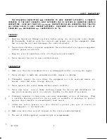
Page 5: ... non ventilated area PREPARATION 1 1 Make s u r e t h a t the attachment d r i v e is disengaged before s t a r t i n g the engine 2 Never attempt t o make any adjustments while engine is running 3 Thoroughly inspect the area where t h e equipment i s t o be used and remove a l l boards wires and o t h e r foreign objects 4 Never operate the r o t a r y broom without good v i s i b i l i t y 5 Nev...

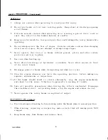
Page 6: ...e when backing up Never direct discharge a t bystanders o r windows Never allow anyone i n f r o n t of t h e r o t a r y broom Disengage power t o broom when transporting or when n o t i n use Stop the engine whenever you leave the operating p o s i t i o n before making any repairs adjustments o r inspections I f the broom should start t o v i b r a t e abnormally s t o p the engine immediately ...

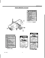
Page 7: ... CAUSE DEATH KEEP PEOPLE AND CLOTHING WELL CLEAR DO NOT OPERATE WITHOUT ALL DRIVELINE TRACTOR AND EQUIPMENT SHIELDS DRIVELINES SECURELY IN PLACE ATTACHED AT BOTH ENDS DRIVELINE SHIELDS THAT TURN FREELY ON DRIVELINE TRANSMISSION ROTATIVE A CARDAN TOUTCO TA T P UT CAUS L A o R PERSONNESY L tCART T E N R A T E ENTS ET NE PAS OPeRER SANS OUE TOUS LES PROTEC TEURS D UTRACTEURDE Le OUlPEMENTETDELhRBRE A...

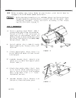
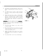
Page 8: ... r p i n i n upper h o l e of each parking stand S e t parking stands i n most extended p o s i t i o n and secure each stand w i t h a 4 m m x 80mm h a i r p i n fig 1 item 2 b I n s t a l l adapter f i g 1 item 3 1 i n s i d e broom female h i t c h Secure with a 5 8 nylon nut C Attach support plate fig 2 item 1 on p i n of lower l e f t hand l i f t l i n k Secure w i t h hairpin d Assemble sha...

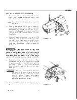
Page 9: ...u l l y Make s u r e d r i v e l i n e is well secured a t both ends B This shaft turns at very high Wl4 If the collar is not 1ocked to the PM shaft at the tractor end or i f the yoke at the broom end is not secured properly the driveline can fly loose w i t h great force capable of causing serious injury or death d Remove h a i r p i n fig 4 item 1 from welded sleeve on r i g h t hand side of bro...

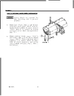
Page 10: ...ig 5 item 3 Select desired number of spacer sleeves fig 5 item 2 t o remain on bottom portion of c a s t e r wheel see application page 10 Remove parking stands f ig 1 item 1 and replace them w i t h t h e c a s t e r wheels fig 5 item 3 Place remaining spacer s l e e v e s1 over caster wheels on upper s i d e of s t a n d s u p p o r t s and s e c u r e c a s t e r wheels w i t h p i n s fig 5 it...

Page 11: ...ush t o ground contact t u r n knob 2 i n a c l o c k w i s e direction Use only t o compensate brush wear I NOTICE 1 Adjust so t h a t broom head when l i f t e d by the f r o n t weighs between 30 5 0 l b s 1 3 5 kg 22 6 kg More than t h i s can cause premature brush wear and overheat gearbox FIGURE 1 3 FRONT W H E E L JACK 3 P u l l knob c o m p l e t e l y outward t o reach approximate height ...

Page 12: ... k e a broom not w i t h t h e sides of the bristles l i k e a mop 1 T h i s broom works best on snow depth of 6 o r less l a r g e amount of snow c a n be moved i f ground speed is reduced 2 To avoid snow being blown back on the t r a c t o r and or operator sweep w i t h the wind blowing i n the d i r e c t i o n of broom discharge 3 The u s e of HONDA approved rear counterweight is recommended ...

Page 13: ...tact your dealer LUBRICATION 1 GEARBOX Check l i q u i d grease l e v e l i n the worm gear d r i v e every week run the broom a minimum of 15 minutes t o warm up the l i q u i d grease and make sure gear box is f i l l e d t o f r o n t l e v e l p l u g I f n e c e s s a r y add SHELL DURINA 0 o r AL VANIA EP 0 liquid grease o r its equivalent D o not o v e r f i l l 2 DRIVELINE Grease as indica...

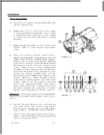
Page 14: ...brush w i t h the p i n s away from the spacer r i n g important pins i n s i d e the zigzag brushes m u s t a l l be positioned on the same brush support cone fig 2 item 611 Place another s p a c e r r i n g and a zigzag brush w i t h the pins fig 2 item 4 on the spacer ring side and so on spacing brushes w i t h spacer rings Must end w i t h a zigzag brush w i t h the pins towards the gear box o...

Page 15: ...t l y raise broom head and lock i n place w i t h hair pin IMPORTANT Once the broom is f u l l y remounted t h i s p i n has t o be set i n i t s most extended p o s i t i o n i n order t o allow the broom t o follow ground variations d Carefully lower broom so i t rest on the storage stands e Disconnect broom d r i v e l i n e from t r a c t o r PTO s h a f t and place d r i v e l i n e on i t s ...

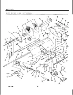
Page 16: ...I PARTS GUIDE F R O N T R O T A R Y BROOM 4 7 M O D E L 65 OM 0180 14 ...

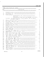
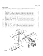
Page 17: ...t e n s i o n 1 B e a r i n g 4 P l a s t i c w h e e l 2 Wheel b u s h i n g 4 Knob 5 1 6 N C 1 P l a s t i c h a n d l e 1 N y l o n w a s h e r 1 1 3 2 d i a h o l e f l a t 1 Wheel c u p 4 B o l t 1 2 NC x 1 3 4 h e x 2 B o l t 5 1 6 N C x 1 2 f l a n g e 2 9 B o l t 5 1 6 NC x 3 4 c a r r i a g e 6 B o l t 1 4 NC x 2 1 2 h e x 1 b r u s h e s i t e m A P i n 3 m m d i a x 65mm h a i r 1 B o l...

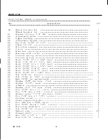
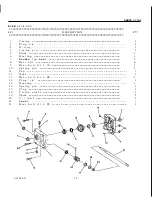
Page 18: ... B o l t 7 1 6 NC x 1 1 4 h e x B o l t 5 1 6 NC x 1 3 4 h e x B o l t 5 1 6 NC x 2 h e x B o l t 5 1 6 NC x 1 h e x B o l t 5 1 6 NC x 3 4 h e x N u t 5 8 N C s t o v e r N u t 7 1 6 N C h e x N u t 7 16 N C n y l o n l o c k Washer 3 8 d i a h o l e f l a t Washer 7 1 6 l o c k A d a p t e r Washer 1 2 d i a h o l e f l a t P i n 3 1 6 d i a x 1 r o l l P i n 1 8 d i a x 3 4 c o t t e r Washer n...

Page 19: ...1 6 N C W a s h e r 1 2 d i a h o l e f l a t G r e a s e f i t t i n g 1 4 NF W a s h e r 5 8 d i a h o l e f l a t W h e e l b r a c k e t B o l t 1 2 NC x 3 1 2 h e x W h e e l c u p W h e e l b u s h i n g B e a r i n g P l a s t i c w h e e l N u t 1 2 NC n y l o n l o c k N u t 5 1 6 NC h e x B o l t 5 1 6 NC x 1 h e x W a s h e r 3 8 d i a h o l e h e x W a s h e r 5 1 6 l o c k 1 2 I OM 01...

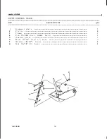
Page 20: ... p o r t p l a t e 1 2 C l e v i s 2 3 C h a i n 1 4 P i n 2 5mm d i a x 40mm h a i r 1 5 A n c h o r p l a t e 1 7 W a s h e r 5 16 l o c k 3 6 B o l t 5 16 NC x l h e x 8 Nut 5 16 N C h e x 3 3 0 OM 0180 18 ...

Page 21: ...g e l l o Shim B e a r i n g Double l i p s e a l Hex n u t Hex b o l t M 8 x 3 0 S p r i n g p i n Cap Gear Hex b o l t M 8 x 6 5 B e a r i n g S p r i n g p i n P l u g 1 4 1 1 2 1 2 2 2 6 2 2 1 1 2 1 2 1 1 7 P l u g 1 1 8 P i n i o n s h a f t 1 1 9 Shim 1 2 0 O i l s e a l 1 2 1 S h a f t 1 2 2 Hex b o l t M 8 x 7 5 2 1 4 7 OM 0180 Is 19 ...

Page 22: ...I n n e r s h i e l d 1 2 N y l o n b e a r i n g 1 3 B e a r i n g r e t a i n e r 1 4 Yoke a n d female s h a f t 1 5 D o u b l e y o k e j o i n t C V 1 6 Yoke 1 1 7 U n i v e r s a l j o i n t k i t 1 OM 0180 20 ...

Page 23: ...Q u i c k c o n n e c t y o k e a s s e m b l y 1 S p r i n g l o c k y o k e r e p a i r k i t 1 U n i v e r s a l j o i n t k i t Yoke a n d male s h a f t a s s e m b l y 1 B e a r i n g r e t a i n e r 2 N y l o n b e a r i n g 2 O u t e r s h i e l d 1 2 OM 0180 21 ...

Page 24: ...P l a s t i c w h e e l W h e e l b u s h i n g Wheel c u p S p a c e r s l e e v e 1 4 l g S p a c e r s l e e v e 1 2 l g S p a c e r s l e e v e 1 l g S p a c e r s l e e v e 1 1 4 l g P i n 5 1 6 d i a x 1 7 1 6 W a s h e r P i n 2 5mm d i a x 40mm h a i r B o l t 1 2 NC x 3 1 2 h e x N u t 1 2 NC n y l o n l o c k 1 4 1 1 4 2 4 4 2 2 6 2 2 2 2 2 2 OM 0180 5 22 ...

Page 25: ... 9 7 9 12 7 9 8 13 6 9 8 19 23 29 8 27 1 35 2 1 M12 1 75 I 28 34 51 59 8T 81 93 2 0 7T M14 49 56 4T 57 66 4T M18 2 0 96 109 67 77 116 130 129 145 I 27 1 33 9 1 hread 7 l 7 Pounds Feel Newton Meters 12 17 16 3 23 19 27 25 7 36 6 t 46 1 54 2 I 1 25 I 35 47 I 47 4 63 7 I 51 5 62 3 40 52 54 2 70 5 37 9 46 1 31 41 42 55 6 69 1 79 9 70 5 86 7 52 64 66 5 75 9 84 101 6 62 75 77 2 89 4 75 9 92 1 56 68 1 25...

Page 26: ......
Page 27: ... Service Department Duluth Georgia 30136 9421 Telephone 404 497 6400 P 0 BOX 100021 W e w i l l need t h e following i n order t o assist you 0 Your name address and telephone number 0 Product model and serial number 0 Date of purchase 0 Dealer name and address 0 Nature of the problem After reviewing a l l t h e f a c t s involved you w i l l be advised of what a c t i o n can be taken Please bear...

Page 28: ...3839339 9106 P r i n t e d i n Canada ...

Reviews: