


41
HONDA O/M ’04 CR250R (E) 31KSK6000 00X31-KSK-6000
1
2
5
2
3
1
4
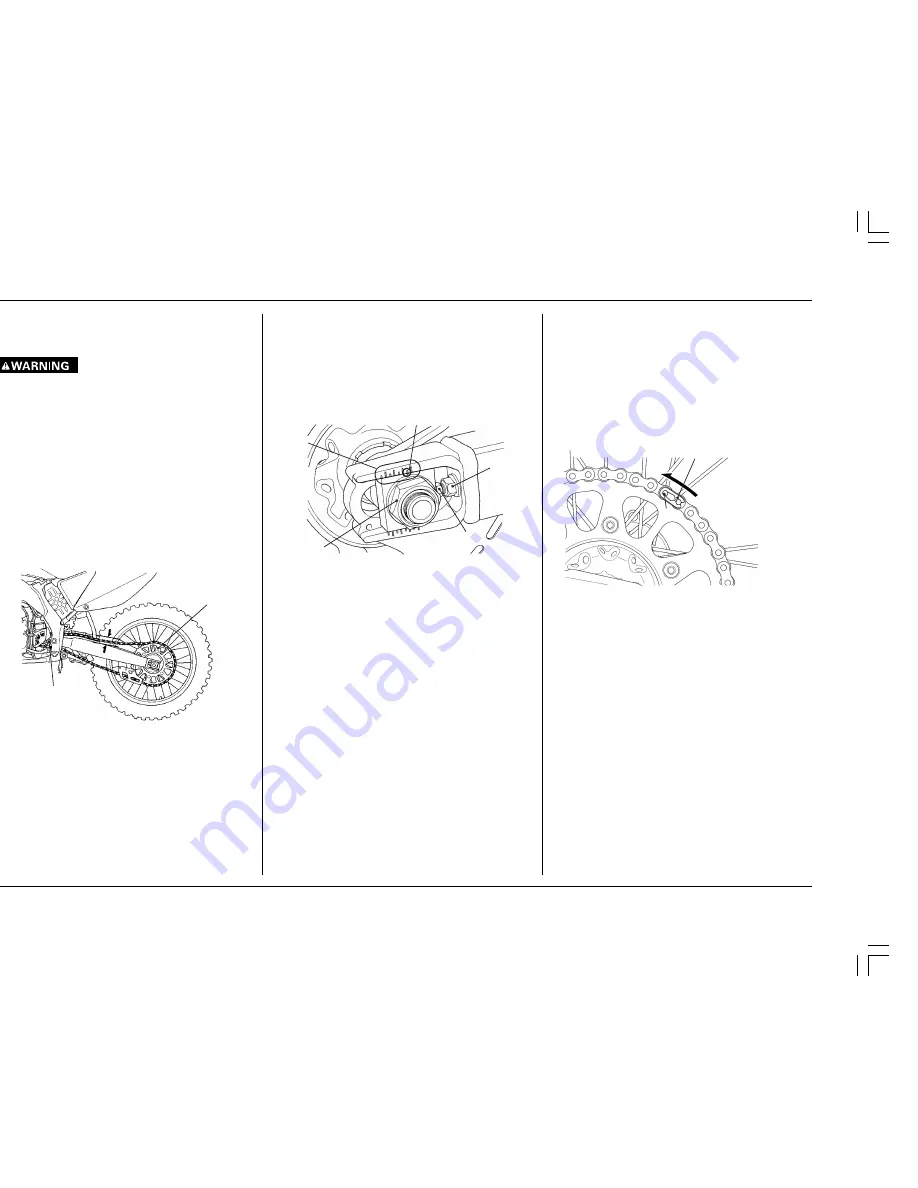
Adjustment
1. Loosen the rear axle nut.
2. Loosen the lock nuts and turn the adjusting bolt
counterclockwise to decrease slack or clockwise to
increase slack.
Align the index mark of the axle plates with the
same reference marks on both sides of the
swingarm.
(1) REAR AXLE NUT
(2) LOCK NUT
(3) ADJUSTING BOLT
(4) INDEX MARK
(5) REFERENCE MARKS
3. Tighten and torque the rear axle nut.
TORQUE: 93 lbf
•
ft (127 N
•
m, 13 kgf
•
m)
4. Recheck chain slack and adjust if necessary.
5. Loosen the adjusting bolt counterclockwise lightly
until it touches the axle plate. Then, tighten and
torque the lock nut by holding the adjusting bolt
with a wrench.
TORQUE: 20 lbf
•
ft (27 N
•
m, 2.8 kgf
•
m)
Removal, Cleaning and Inspection
For maximum service life, the drive chain should be
cleaned, lubricated, and adjusted before each outing.
1. Carefully remove the master link retaining clip with
pliers.
Remove the master link and drive chain.
2. Clean the drive chain in high flash-point solvent and
allow it to dry. Inspect the drive chain for possible
wear or damage. Replace any chain that has dam-
aged rollers, loose or tight fitting links, or otherwise
appears unserviceable.
(1) RETAINING CLIP
(2) MASTER LINK
3. Inspect the sprocket teeth for possible wear or
damage.
Replace if necessary.
NOTE:
•
Never install a new drive chain on badly worn
sprockets, or use new sprockets with a badly worn
drive chain. Both chain and sprockets must be in
good condition, or the new replacement chain or
sprocket(s) will wear rapidly.
•
Excessively worn sprocket teeth have a hooked,
worn appearance. Replace any sprocket which is
damaged or excessively worn.
DRIVE CHAIN
Regular cleaning, lubrication, and proper adjustment
will help to extend the service life of the drive chain.
•
Take care to prevent catching your fingers be-
tween the chain and sprocket.
Inspection
1. Turn the engine off, raise the rear wheel off the
ground by placing the optional workstand or equiva-
lent support under the engine and shift the trans-
mission into neutral.
2. Check slack in the drive chain midway between the
sprockets, above the swingarm. Drive chain slack
should allow 1 — 1-3/8 in (25 — 35 mm) of vertical
movement.
NOTE:
•
Excessive chain slack may allow the drive chain to
damage the engine cases.
(1) DRIVE SPROCKET
(2) DRIVEN SPROCKET
(3) DRIVE CHAIN SLACK
If the chain is found to be slack in one segment of its
length and taut in another, this indicates that some of
the links are either worn, kinked or binding. Kinking and
binding can frequently be eliminated by thorough clean-
ing and lubrication. If the drive chain requires adjust-
ment, the procedure is as follows:
1
2
*CR250R (E) P034-043
12/10/03, 4:46 PM
41


