background image

8

Assembly - Hanging the Fan

Attaching the fan to the electrical 
box

Hanging the fan


Pass the 120-Volt supply wires through the center hole in the 
slide-on mounting bracket (A).


Install the ceiling slide-on mounting bracket (A) on the outlet 
box by sliding the slide-on mounting bracket (A) over the two 
screws (JJ) provided with the outlet box. If necessary, use leveling 
washers (not included) between the slide-on mounting bracket 
(A) and the outlet box. Note that the flat side of the slide-on 
mounting bracket (A) is toward the outlet box.


Securely tighten the two mounting screws (JJ).


Carefully lift the fan-motor assembly (E) up to the slide-on 
mounting bracket (A).


Seat the hanger ball portion of the ball/downrod assembly (D) 
in the mounting bracket socket. Ensure that the tab on the 
slide-on mounting bracket (A) socket is properly seated in the 
groove in the hanger ball.

1

2

WARNING:

 To reduce the risk of fire, electric shock, or other 

personal injury, mount the fan to an outlet box or supporting 

system marked “Acceptable for fan support of 35 lbs. 

(15.9kg) or less” and use the mounting screws provided 

with the outlet box.

NOTE:

 The mounting bracket (A) is designed to slide into place 

on an outlet box with the outlet box screws (JJ).

A

JJ

JJ

A

B

E

C

D

WARNING:

 When using the standard ball/downrod mounting, 

the tab in the ring at the bottom of the mounting bracket 

must rest in the groove of the hanger ball. Failure to properly 

seat the tab in the groove may result in fan wobble issues 

and potentially damage the wiring.

Summary of Contents for CONNOR 51847

Page 1: ...enhance your home Visit us online to see our full line of products available for your home improvement needs Thank you for choosing Home Decorators Collection Item 1003 316 478 1003 316 497 Model 51847 51848 UL Model EF200S R 54 USE AND CARE GUIDE CONNOR 54 INCH CEILING FAN To view an instructional video on how to install this product 1 Go to www homedepot com and enter either the Item or Model nu...

Page 2: ... electricity off at the main fuse box before wiring If you feel you do not have enough electrical wiring knowledge or experience contact a licensed electrician WARNING Electrical diagrams are for reference only Optional use of any light kit shall be UL listed and marked suitable for use with this fan Safety Information Table of Contents CAUTION To reduce the risk of personal injury use only the sc...

Page 3: ... is not covered by this warranty Because of varying climatic conditions this warranty does not cover any changes in brass finish including rusting pitting corroding tarnishing or peeling Brass finishes of this type give their longest useful life when protected from varying weather conditions A certain amount of wobble is normal and should not be considered a defect Servicing performed by unauthori...

Page 4: ... continued HARDWARE INCLUDED NOTE Hardware not shown to actual size CC BB DD AA PP OO Part Description Quantity AA Leadwire 1 BB Plastic wire connector 3 CC Hanging pin 1 DD Locking pin 1 OO Wall mount screws 2 PP Plug 1 ...

Page 5: ...anopy 1 C Canopy bottom cover 1 D Ball downrod assembly 1 E Fan motor assembly 1 F Light kit fitter assembly 1 G Glass bowl 1 Part Description Quantity H Blade 5 I Blade arm 5 J LED bulb 2 K Remote control battery included 1 L Receiver 1 M Wall bracket 1 IMPORTANT This product and or components are governed by one or more of the following U S Patents 5 947 436 5 988 580 6 010 110 6 046 416 6 210 1...

Page 6: ...se the appropriate fasteners and materials The outlet box and its bracing must be able to fully support the weight of the moving fan at least 35 lbs Do not use a plastic outlet box The illustrations below show three different ways to mount the outlet box If the canopy B touches the ball downrod assembly D then remove the decorative canopy bottom cover C and turn the canopy B 180 before attaching t...

Page 7: ...ttom of the mounting bracket A and turn the canopy counterclockwise to remove the mounting bracket A from the canopy B Assembling the fan Loosen but do not remove the 2 setscrews ZZ on the collar on top of the motor housing E Align the holes at the bottom of the downrod D with the holes in the collar on top of the motor housing E Carefully insert the hanger pin CC through the holes in the collar a...

Page 8: ...A Seat the hanger ball portion of the ball downrod assembly D in the mounting bracket socket Ensure that the tab on the slide on mounting bracket A socket is properly seated in the groove in the hanger ball 1 2 WARNING To reduce the risk of fire electric shock or other personal injury mount the fan to an outlet box or supporting system marked Acceptable for fan support of 35 lbs 15 9kg or less and...

Page 9: ...your fan Secure the connectors with electrical tape and ensure there are no loose strands or connections WARNING Each wire nut supplied with this fan is designed to accept up to one 12 gauge house wire and two wires from the fan If you have larger than 12 gauge house wiring or more than one house wire to connect to the fan wiring consult an electrician for the proper size wire nuts to use Spread t...

Page 10: ...se to lock in place Assembly Hanging the Fan continued 5 Wiring the fan to the receiver If using the 4 5 in ball downrod assembly D provided wire the receiver to the fan wires by connecting the molded adaptor plug from receiver L with molded adaptor of the fan motor assembly E together If you wish to use longer downrod you can use the extension lead wire 42 in AA provided by connecting the molded ...

Page 11: ...ade H with the three posts on the top of the blade brackets I Hold the blade H close to the blade bracket I and press the blade H down firmly Ensure the key slot holes are properly seated on the blade arm posts While still holding the blade H down firmly slide the blade H away from the bracket I side until the blade H engages in the locking mechanism Make sure the locking mechanism at the rear of ...

Page 12: ...ic shock disconnect the electrical supply circuit to the fan before installing the light kit F E HH II Installing the glass bowl 2 CAUTION Make sure the power is off before attaching or removing the glass bowl WARNING Allow the glass bowl to cool completely before removing KK VV E G J F Remove the glass bowl holder KK from the threaded nipple of the light kit fitter assembly F With the power off i...

Page 13: ...light kit fitter assembly F by removing the center hex nut NN inside the switch cap WW and then thread the switch cap WW off the threaded nipple on the top of the light kit fitter assembly F Press the plastic plug PP provided into the center hole of the switch cap WW Remove and save the three light kit mounting screws HH on the switch cap WW Slide the switch cap WW into the switch housing XX and r...

Page 14: ...ontrol has already been paired to the ceiling fan for your convenience If you have two of the same model fans in your home please follow the steps below to control each fan independently K M OO Confirm that the power to the fan is off at either the wall switch or breaker box Return power to the fan at the wall switch or breaker box Install one 3V Lithium Battery included Press and release the Lear...

Page 15: ...oling effect This allows you to set your air conditioner on a warmer setting without affecting your comfort Cool weather Reverse An upward airflow moves warm air off of the ceiling This allows you to set your heating unit on a lower setting without affecting your comfort A Warm weather B Cool weather NOTE Wait for the fan to stop before reversing the direction of the blade rotation USING THE REMOT...

Page 16: ...n the ceiling above the tip of one of the blades Measure from a point on the center of each blade to the point on the ceiling Rotate the fan until the next blade is positioned for measurement Repeat for each blade Any measurement deviation should be within 1 8 in Run the fan for ten minutes If the fan continues to wobble please contact Customer Service and a balancing kit will be sent to you at no...

Page 17: ...blems missing parts Before returning to the store call Home Depot Customer Service 8 a m 7 p m EST Monday Friday 9 a m 6 p m EST Saturday 1 800 986 3460 HOMEDEPOT COM HOMEDECORATORS Retain this manual for future use ...

Page 18: ... del hogar Visítanos por Internet para ver nuestra línea completa de productos disponibles a fin de satisfacer la necesidades de mejoras de tu hogar Gracias por elegir Home Decorators Collection Artículo 1003 316 478 1003 316 497 Modelo 51847 51848 Modelo UL EF200S R 54 GUÍA DE USO Y MANTENIMIENTO VENTILADOR DE TECHO CONNOR 54 PLG 1 3 M To view an instructional video on how to install this product...

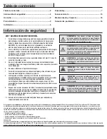
Page 19: ...pas ADVERTENCIA Para evitar una posible descarga eléctrica hay que desconectar la electricidad en la caja principal de fusibles antes cablear En caso de no tener suficiente experiencia o conocimientos sobre cableado eléctrico hay que contratar a un electricista con licencia ADVERTENCIA Los diagramas eléctricos son solo para referencia Cualquier juego de luces opcional debe estar aprobado por UL y ...

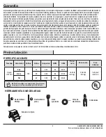
Page 20: ...i por fijación de cualquier accesorio Puesto que las condiciones climáticas pueden variar esta garantía no cubre ningún cambio del acabado en latón como óxido perforación corrosión manchas o descascaramiento Este tipo de acabados en latón alargan la vida útil al proteger contra las condiciones climáticas cambiantes Cierta oscilación es normal y no debe considerase un defecto Cualquier servicio pre...

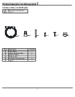
Page 21: ...JES NOTA Los herrajes no se muestran en tamaño real CC BB DD AA PP OO Pieza Descripción Cantidad AA Cable conductor 1 BB Conector plástico para cables 3 CC Pasador de soporte 1 DD Pasador de cierre 1 OO Tornillo para el soporte de pared 2 PP Conector 1 ...

Page 22: ...ubierta 1 D Conjunto del tubo bajante bola 1 E Conjunto motor ventilador 1 F Conjunto del soporte del kit de luces 1 G Tazón de vidrio 1 Pieza Descripción Cantidad H Aspa 5 I Brazo del aspa 5 J Bombilla LED 2 K Control remoto incluye batería 1 L Receptor 1 M Soporte de pared 1 IMPORTANTE Este producto y o sus componentes están protegidos por una o más de las siguientes patentes de los EE UU 5 947 ...

Page 23: ...a sostener completamente el peso en movimiento del ventilador al menos 35 lb 15 9 kg No usar una caja eléctrica de plástico Las ilustraciones más abajo muestran tres formas distintas de montar la caja eléctrica Si la cubierta B toca el conjunto del tubo bola bajante D hay que retirar la tapa inferior decorativa C de la cubierta y girar esta B 180º antes de fijarla B a la placa de montaje Para colg...

Page 24: ...ontaje A y girar la cubierta hacia la izquierda para quitar aquel A de esta B Cómo ensamblar el ventilador Aflojar sin quitarlos los 2 tornillos de fijación ZZ del collarín en la parte superior de la carcasa de motor E Alinear los orificios en la parte inferior del tubo bajante D con aquellos del collarín en la parte superior de la carcasa de motor E Insertar con cuidado el pasador de soporte CC a...

Page 25: ...orte del conjunto del tubo bajante bola D en el casquillo del soporte de montaje Asegurar que la pestaña en el casquillo del soporte de montaje deslizante A encaje bien dentro de la ranura de la bola de soporte 1 2 ADVERTENCIA Para reducir el riesgo de incendio descarga eléctrica o lesiones personales instalar sólo en una caja eléctrica o sistema de soporte clasificado como apropiado para sostener...

Page 26: ...BB que vienen con el ventilador Sujetar los conectores con cinta de electricista y garantizar que no haya conexiones ni cables sueltos ADVERTENCIA Cada tuerca para cable suministrada con este ventilador está diseñada para aceptar un cable doméstico de calibre 12 o menos y dos cables del ventilador Si el cableado doméstico excede del calibre 12 o tiene más de un cable para conectar al cableado del ...

Page 27: ...ventilador continuación 5 Cómo cablear el ventilador al receptor Al usar el conjunto del tubo bajante bola D de 4 5 plg 11 4 cm incluido hay que conectar los cables del receptor a los cables del ventilador uniendo el enchufe del adaptador moldeado del receptor L con el adaptador moldeado del conjunto motor ventilador E Si se desea un tubo bajante más largo puede usarse la extensión de cable conduc...

Page 28: ...H con los tres postes de la parte superior de este I Sostener el aspa H cerca de su soporte I y presionarla H hacia abajo con firmeza Asegurar que los orificios tipo ojo de cerradura queden bien apoyados sobre los postes del brazo del aspa Mientras se sujeta el aspa H deslizarla H hacia el lado opuesto del soporte I con firmeza hasta que aquella H se acople al mecanismo de cierre Asegurar que el m...

Page 29: ...esgo de descarga eléctrica desconectar el circuito de energía del ventilador antes de instalar el kit de luces F E HH II Cómo instalar el tazón de vidrio 2 PRECAUCIÓN Asegurar que la corriente esté cortada antes de montar o retirar el tazón de vidrio ADVERTENCIA Esperar que el tazón de vidrio se enfríe completamente antes de retirarlo KK VV E G J F Retira el soporte del tazón KK del ensamblaje del...

Page 30: ...uerca hexagonal del centro NN dentro de dicha cubierta WW y desenroscándola WW de la boquilla roscada en la parte superior del conjunto del soporte del kit de luces F Presionar el tapón plástico PP incluido dentro del orificio central de la cubierta de la caja del interruptor WW Quitar y guardar los tres tornillos de montaje del kit de luces MM de la cubierta de la caja del interruptor WW Deslizar...

Page 31: ...tilador de techo para tu conveniencia Si tienes dos ventiladores del mismo modelo en tu hogar sigue los pasos más abajo para controlar cada ventilador por separado K M OO Confirmar que la electricidad del ventilador está desconectada en el interruptor de pared o en la caja de cortacircuitos Conectar la electricidad al ventilador usando el interruptor de pared o en la caja de cortacircuito Instala ...

Page 32: ...o permite configurar el equipo de aire acondicionado a temperatura más alta sin afectar el confort Clima frío Reversa Un flujo de aire hacia arriba desplaza el aire cálido del cielo raso Esto te permite fijar la unidad de calefacción en configuración más baja sin afectar el confort A Clima cálido B Clima frío NOTA Esperar a que se detenga el ventilador antes de invertir el sentido de giro de las a...

Page 33: ...icar este nivel seleccionando un punto en el cielo raso sobre la punta de una de las aspas Medir desde un punto en el centro de cada aspa al punto en el cielo raso Girar el ventilador hasta que la siguiente aspa quede en posición para medir Repetir el procedimiento con cada aspa Las desviaciones de la medición no deben pasar de 1 8 plg 0 3 cm Dejar que el ventilador funcione durante diez minutos S...

Page 34: ... de devolver a la tienda llamar al servicio al cliente de The Home Depot De lunes a viernes entre 8 00 a m y 7 00 p m Este y los sábados de 9 00 a m a 6 00 p m Este 1 800 986 3460 HOMEDEPOT COM HOMEDECORATORS Conservar este manual para uso futuro ...

Reviews: