background image


CONNECTING TO OMNI IIe, LUMINA, OMNIPRO II, AND LUMINA PRO 
 

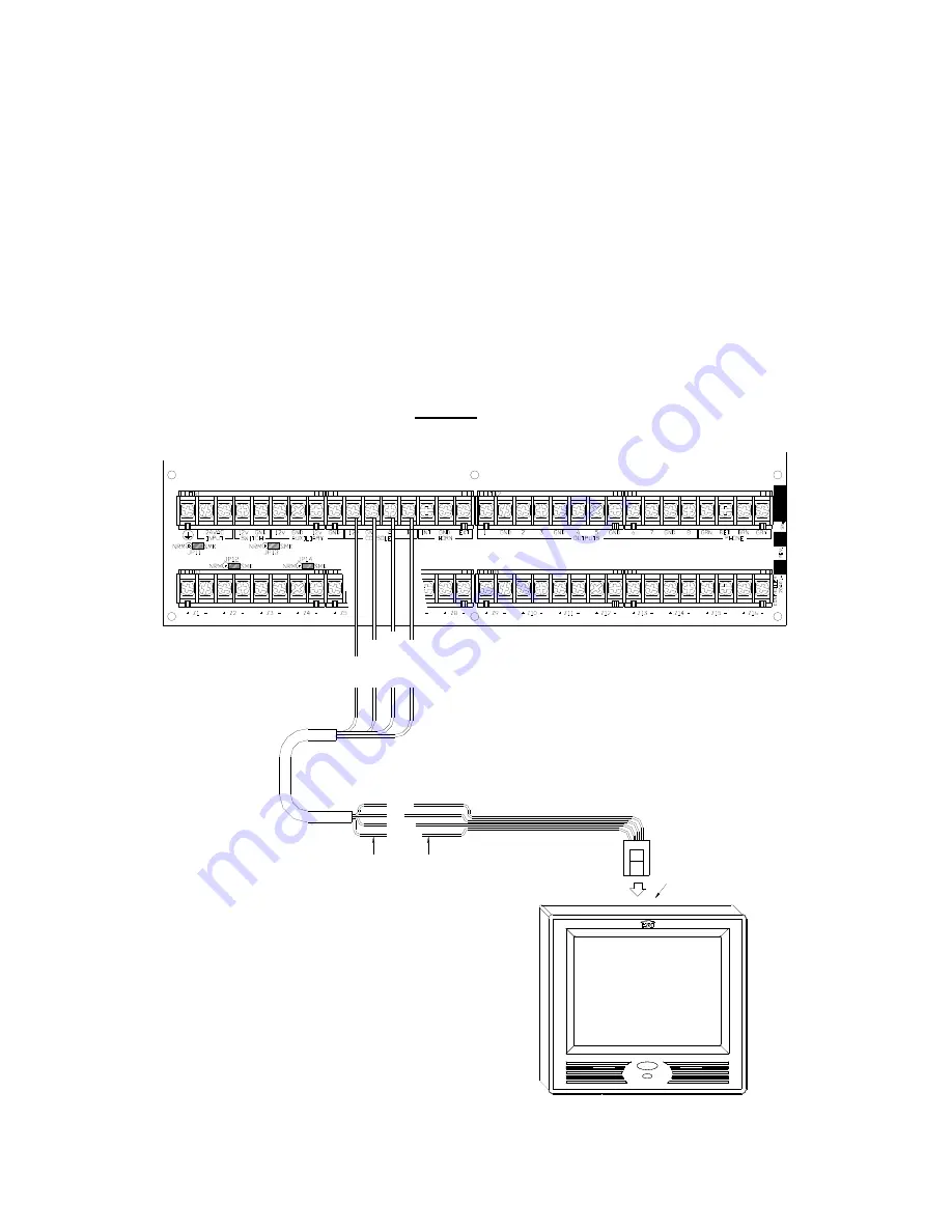
Connect the "Yellow" and "Green" wires from the touchscreen to the "A" and "B" terminals 
under the section marked "CONSOLE" on the controller, respectively.  Connect the "Red" and 
"Black" wires from the touchscreen to the "12V" and "GND" terminals under the section 
marked "AUXILIARY" on the controller, respectively.   
 
A maximum combination of 8 touchscreens and consoles can be used with Omni IIe or Lumina 
and a maximum combination of 16 with OmniPro II or Lumina Pro. 

 
NOTE: Do not exceed the maximum current limitation of the controller.  If more than 2 
touchscreens are used, the additional touchscreens must be powered from an external 
power supply or HAI Touchscreen Hub. 


THE EXTERNAL POWER SUPPLY MUST BE GROUNDED TO THE CONTROLLER 
EARTH GROUND TO AVOID DAMAGE TO THE TOUCHSCREEN. 

GR

EE

N

YE

L

LOW

BL

AC

K

RE

D

CONNECT ENDS OF SUPPLIED
CABLE TO CORRESPONDING ENDS
OF THE POWER/COMMUNICATION
CABLE FROM THE CONTROLLER

YELLOW

GREEN

BLACK
RED

(PLUGS INTO J1)

SUPPLIED CABLE


Omni IIe, Lumina, OmniPro II, and Lumina Pro Connections


Summary of Contents for OmniTouch 53A00-1

Page 1: ...Home Automation Inc Model 53A00 1 OmniTouch 5 7 Touchscreen with Video Installation Manual Document Number 53I00 1 Rev A June 2007...

Page 2: ...s device may not cause harmful interference and 2 This device must accept any interference received including interference that may cause undesired operation Verified to comply with the limits of a Cl...

Page 3: ...to the HAI controller run the power communications cable as determined by Table 1 from the controller location to touchscreen location A minimum of 4 wires is required for operation 2 for power and 2...

Page 4: ...the controller and each touchscreen is 800 feet Terminate both ends of the Cat 5 cable with an 8 position modular connector as if to make a standard network cable Note When calculating the distance b...

Page 5: ...ch hole as shown as shown Carefully cut along the pencil line DO NOT OVERSIZE THIS CUTOUT Figure 1 2 Remove the faceplate Remove the faceplate from the touchscreen by grasping the top and bottom edges...

Page 6: ...own in Figure 3 Figure 3 4 Install the backbox into the cutout in the wall a Insert the communications cable through the rectangular cutout in the touchscreen backbox b Locate the retaining flange scr...

Page 7: ...ular cable assembly Attach the wires coming from the controller to the supplied cable assembly using the supplied wire spice connectors b When connecting the touchscreen to the HAI Touchscreen Hub ter...

Page 8: ...6 Figure 6 7 Install the touchscreen assembly a Align the tabs on the touchscreen assembly with the slots on the backbox Figure 7...

Page 9: ...faceplate onto the touchscreen by hanging the top of the faceplate on the top edge of the touchscreen then gently snapping the bottom onto the touchscreen REMOVING THE TOUCHSCREEN After installation...

Page 10: ...i IIe or Lumina and a maximum combination of 16 with OmniPro II or Lumina Pro NOTE Do not exceed the maximum current limitation of the controller If more than 2 touchscreens are used the additional to...

Page 11: ...ens and consoles can be used with OmniLT NOTE Do not exceed the maximum current limitation of the controller If more than 1 touchscreen is used the additional touchscreens must be powered from an exte...

Page 12: ...een if the touchscreen isn t addressed properly other consoles or touchscreens already occupy the touchscreen address or isn t communicating with the controller the following page is displayed To assi...

Page 13: ...and exit Once the touchscreen is properly configured and communicating with the controller other configuration items may be configured using the Screen Setup page To access the Screen Setup page from...

Page 14: ...The Update Port is a USB port in the lower right section of the touchscreen Load the update file on a USB thumb drive Plug the thumb drive into the USB Update Port on the OmniTouch 5 7 Touchscreen Whe...

Page 15: ...rea 4 626 W x 3 492 H Voltage Operating Voltage 10 24 VDC Maximum Current Consumption at 12 VDC 300 mA based on Maximum Cable Length as defined in Table 1 Maximum Current Consumption at 24 VDC 200 mA...

Page 16: ......

Reviews: