HOLUND FST-C50HD30-2 User Manual Download Page 5

4 / 16

2.2 Underwater Lamp

Underwater lamp is a lighting device, mainly consisting of cylinder and cables. It is designed to offer lighting support for
camera shooting in low-light underwater environments.

Depth of work

50m

Size

Ö

65×110mm(cables excluded)

Weight

1Kg( in open air, cables excluded)

Light color

940nm infrared light

LED power

3W*5

Power

24V DC

2.3 Rotative cleaning brush

The rotative cleaning brush is used to clean the front-end windows of the underwater camera and underwater lamp. It

can achieve fixed-angle rotative movement within a plane, and thus automatically brush the surfaces of the underwater

optical instruments at the set time, satisfying the long-duration operation demand of the system.

3. System assembly

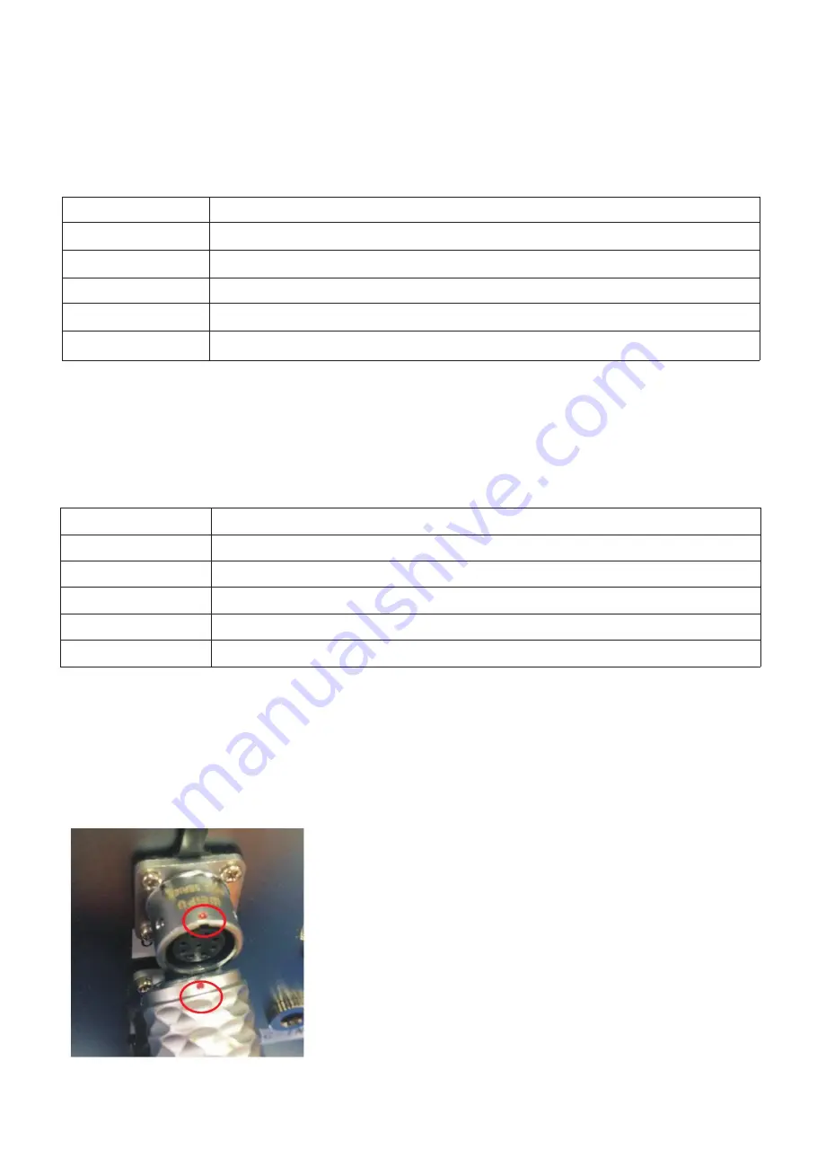
3.1 How to plug in the equipment

Match the red dot on the equipment plug to the red dot on the socket and press it hard to make the connection until a

crisp sound is heard.

Depth of work

50m

Size

Ö

36×220mm

cables and cleaning brush swing arms are not included

The range of clean

R30-95mm

Rotating angle

140°

Weight

700g

in air, cables excluded

Power

24V 5W

Summary of Contents for FST-C50HD30-2

Page 1: ...User Manual FST C50HD30 2 Digital Underwater Camera including brush Holund vnr 152 971 ...

Page 2: ...ct the equipment to the control box 6 4 System operation 7 4 1 Operation of camera 7 4 2 Configuration Management 7 4 3 The display of video 8 4 4 The recording of video 9 4 5 The usage of lamp 10 4 6 The usage of the cleaning brush 10 5 System use and maintenance 11 5 1 Precautions 11 5 2 Rinse after use 11 Appendix I Description of how to modify a computer IP 11 Appendix II How to install the SE...

Page 3: ...st carefully check to ensure that each part of the equipment is intact or connected properly 4 Do not look directly at the illumination position of the underwater lamp after its turn on to avoid any eye discomfort 5 Do not use this equipment for any other purpose We shall bear no liability resulting from this Do not modify this equipment We shall not be responsible for any accident caused by such ...

Page 4: ...nt It mainly consists of cylinder and cables Largely applied for underwater fixed point video monitoring it can transmit high definition videos from the fixed point to the connected computer to realize real time monitoring and video recording Depth of work 50m Size Ö65 100mm cables excluded Weight 1Kg in open air cables excluded Photosensitive elements 1 3 CMOS Focal 2 8mm f ixed focal Maximum res...

Page 5: ...indows of the underwater camera and underwater lamp It can achieve fixed angle rotative movement within a plane and thus automatically brush the surfaces of the underwater optical instruments at the set time satisfying the long duration operation demand of the system 3 System assembly 3 1 How to plug in the equipment Match the red dot on the equipment plug to the red dot on the socket and press it...

Page 6: ...ow to connect the equipment to the test transfer cable Connect the equipment plug to the test transfer socket Please refer to 3 1 How to plug in the equipment for connection method above Connect the other end of the test cable to the power adapter and the network cable respectively see pics below Now the connectionis completed ...

Page 7: ...omponents to the control box Step 2 Connect the network cable to the control box ports Step 3 Connect the power cord to the DC power ports of the control box Ensure that each connection is reliable fixed Here s a user s real example Note Use a stable DC 24V power supply to power the system Keep the control box away from water and keep the plugs and sockets dry ...

Page 8: ...2 Configuration Management 1 Open Seetong video monitoring user end software Initial login window will show the following Account admin password 123456 Tick Auto Login to save your password This dialog box will not pop up when you run Seetong next time Tick Remember password to save the password and you won t have to enter the password next time 2 Afteropen ing the software click DeviceManage and ...

Page 9: ...he display of video Click the Main View tab on the tab bar to display the image as shown below which means the camera has been successfully added to the equipment list Double click on the IP to display the image ...

Page 10: ...ing the camera and displaying the video 4 4 The recording of video Rightclickon thevideowindowandthefollowinglistwillappear select ManualRecording andleftclick A green VCR appears in the upper right corner of the video as shown indicating that recording begins ...

Page 11: ...yedin the windowis the save path of the video reading the video accordingto thepath 4 5The usageof lamp Turn the lights on and off by powering on and off the lighting adapter 4 6 The usage of the cleaning brush The cleaning brush conducts left and right cleaning movements for 6 times by default after being switched on and then goes into standby Turn off the power to turn it off ...

Page 12: ...ble Do not collision the equipment to avoid damaging the glass 5 2 Rinse after use After each use of the underwater camera in seawater rinse with fresh water to prevent possible erosion damage to the system causedby seawater After rinsing it can be stored by dryingor wipingwith a soft cloth Appendix I Description of how to modify a computer IP This note uses the WINDOWS 10 system as the primary ta...

Page 13: ...12 16 Step 2 Click Network Internet and click change adapter options Step3 Rightclickon the Ethernet thenclick Properties ...

Page 14: ...13 16 Step 4 Double click Internet Protocol Version 4 TCP IPv4 Step 5 Configure the IP address to 192 168 0 221 and the default gateway to 192 168 0 1 Thenclick OK ...

Page 15: ...esponding selectioninterfaceaccording to the operatingsystemlanguageusedby the currentcomputer The followingfigureshowsthe languageselectioninterfacethat appearsintheChineseversionoftheoperatingsystem Thespecificoperationisasfollows Step 1 Select the installation language English Then the welcome wizard interface appears As shown in the following image ...

Page 16: ...15 16 Step2 Click Next to selecttheinstallationdirectory As shownin thefigurebelow ...

Page 17: ...16 16 Step3 Click Install andtheinstallationis completeas shownin thefigure ...

Reviews: