


HT67F86A Internal RTC Application Guidelines
AN0448E V1.00
3/7
January 16, 2017
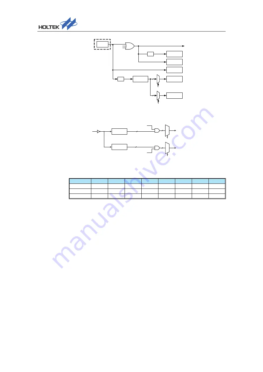
Low Speed
Oscillator
f
SUB
f
SUB
LCD
WDT
f
LXT
Prescaler
TB0[2:0]
f
LXT
/4
Time Base 1
TB1[2:0]
LXT
f
LXT
IDLE2
SLEEP
1/4
Time Base 0
f
SUB
LVR
1/8
f
LCD
Device Clock Configuration
f
LXT
/4
Prescaler 0
f
PSC
f
PSC
/2
8
~ f
PSC
/2
15
M
U
X
M
U
X
TB0[2:0]
TB1[2:0]
Time Base 0 Interrupt
Time Base 1 Interrupt
TB0ON
TB1ON
Prescaler 1
f
PSC
/2
8
~ f
PSC
/2
15
Time Base Interrupt
TB0C Register
Bit
7
6
5
4
3
2
1
0
Name
TB0ON
— — — —
TB02
TB01
TB00
R/W
R/W — — — — R/W
R/W
R/W
POR
0 — — — — 0 0 0
Bit 7
TB0ON
: Time Base 0 Enable Control
0: Disable
1: Enable
Bit 6~3 Unimplemented, read as “0”
Bit 2~0
TB02~TB00
: Time Base 0 time-out period selection
000: 2
8
/f
PSC
001: 2
9
/f
PSC
010: 2
10
/f
PSC
011: 2
11
/f
PSC
100: 2
12
/f
PSC
101: 2
13
/f
PSC
110: 2
14
/f
PSC
111: 2
15
/f
PSC
The
f
PSC
is derived from the internal clock source f
LXT
/4.


