background image


877-012/-112 

P2008 © Firma WJG, Braunschweig. Nachdruck oder Vervielfältigung  nur mit ausdrücklicher Genehmigung 


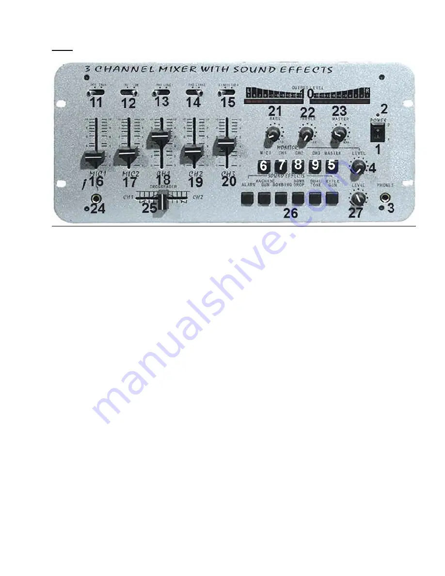
Front: 


1. POWER: On-/Off-switch. 
2. LED of the operation display. 
3. PHONES: TRS-connector for headphones. 

4. MONITOR LEVEL: Volume control for the headphone output [3]. 

5. MONITOR MASTER: Applies the whole output signal to the headphone output [3]. 

6. MONITOR MIC: Applies the microphone signal to the headphone outlet [3]. 

7. MONITOR CH1: Applies the signal from channel 1 to the headphone outlet [3]. 
8. MONITOR CH2: Applies the signal from channel 2 to the headphone outlet [3]. 

9. MONITOR CH3: Applies the signal from channel 3 to the headphone outlet [3]. 

10. OUTPUT LEVEL: VU-meter with LEDs indicates the signal strength at the signal output. 

11. OFF/TALK: If this switch is put to TALK all signal source will be reduced to 12 dB except MIC1 [24]. (Ideal to  

     make talkover annoucments) 
12. HI/LOW: Put this switch to HI if there is a microphone with high impedance connected to MIC2 [28]. 
13. PH1/LINE1: If the signal source of channel 1 is a turn table put this switch to PH1. Otherwise to LINE1. 

14. PH2/LINE2: If the signal source of channel 2 is a turn table put this switch to PH1. Otherwise to LINE2. 

15. LINE3/LINE4: Toggle for the signal inputs of channel 3. 

16. MIC1: Volume control for the microphone on MIC1. 

17. MIC2: Volume control for the microphone on MIC2. 

18. CH1: Volume control of channel 1. 
19. CH2: Volume control of channel 2.  

20. CH3: Volume control of channel 3.  

21. BASS: Controller for the low-pass filter at the signal output. 

22. TREBLE: Controller for the high-pass filter at the signal output. 
23. MASTER: Volume control of the signal output. 

24. TRS-connector for the microphone on MIC1. 
25. CROSSFADER: Slide switch for cross fade from channel 1 to channel 2 or vice versa. 

26. SOUNDEFFECTS: If pressed one time it creates a single sequence of the particular effect. Hold the button  

      and get a permanent effect. There are sic different sound effects available. 

27. Volume control of the sound effects. 


Summary of Contents for MX-3 FX

Page 1: ...len zusammen Getrennte Klangregler für alle 4 Kanäle inklusive separater Umschalter Eingänge und Ausgänge über Cinchstecker Betriebszustände werden durch Leuchtdioden angezeigt Das Mischpult hat Talkover und Crossfader Funktion Das Gerät besitzt vor Überlastung geschützte Schaltkreise Sicherheitshinweise Überprüfen Sie vor Inbetriebnahme das Gerät auf Beschädigungen sollte dies der Fall sein bitte...

Page 2: ...2 28 ein Mikrofon mit hoher Impedanz angeschlossen muss dieser Schalter auf HI gestellt werden 13 PH1 LINE1 Wenn die Signalquelle auf Kanal 1 ein Plattenspieler ist muss dieser Schalter auf PH1 gestellt werden Ansonsten auf LINE1 14 PH2 LINE2 Wenn die Signalquelle auf Kanal 2 ein Plattenspieler ist muss dieser Schalter auf PH2 gestellt werden Ansonsten auf LINE2 15 LINE3 LINE4 Umschalter für die S...

Page 3: ...nal 1 30 INPUT CH2 Analoger Cinchanschluss für einen Plattenspieler PHONO2 oder eine sonstige Audiosignalquelle LINE2 auf Kanal 2 31 INPUT CH3 Analoger Cinchanschluss für zwei Audiosignalquellen LINE3 LINE4 auf Kanal 3 32 OUTPUT Ausgang zum Verstärker des Hauptsoundsystems AMP und Ausgang zu einem Aufzeichnungsgerät REC um das Ausgangssignal aufzunehmen 33 Erdung für die Plattenspieler 34 FUSE 0 5...

Page 4: ...ines and routes signals of different sound sources It has separated adjuster every channel as well as separated toggles Input and output terminals with cinch jacks The operating state will be indicated bu LEDs The mixer has cue crossfader and talkover function Circuit is protected of current overload Security Advices Before using the device please check it for any possible damages In case of damag...

Page 5: ...itch to HI if there is a microphone with high impedance connected to MIC2 28 13 PH1 LINE1 If the signal source of channel 1 is a turn table put this switch to PH1 Otherwise to LINE1 14 PH2 LINE2 If the signal source of channel 2 is a turn table put this switch to PH1 Otherwise to LINE2 15 LINE3 LINE4 Toggle for the signal inputs of channel 3 16 MIC1 Volume control for the microphone on MIC1 17 MIC...

Page 6: ...l 1 30 INPUT CH2 Analogue cinch connector for a turn table PHONO2 or a sundry audio signal source LINE2 on channel 2 31 INPUT CH3 Analogue cinch connector for two audio signal sources LINE3 LINE4 on channel 3 32 OUTPUT Signal output to the amplifier of the main sound system AMP and signal output to a recorder REC to record the output signal 33 Grounding for a turn table 34 FUSE 0 5A Fuse 35 POWER ...

Reviews: