background image

monty 3650


Betriebsanleitung   Operator’s Manual   Notice d’ utilisation


Modéle:  

monty 3650 

_DE-EN-FR_ Release December 2018 

HOFMANN behält sich das Recht zu Änderungen ohne Vorankündigung vor _ HOFMANN reserves the right of modification without notice _ Document non contractuel


51

4.0 COMMANDES 

 
Avant d’utiliser la machine, s’assurer que l’on a bien 
compris  la  façon  de  procéder  et  la  fonction  de 
toutes les commandes. 
 

A.


Pour  allumer  la  machine,  tourner  l’interrupteur 
général  sur  1:  le  moteur  de  la  pompe 
hydraulique  se  met  en  marche  et  reste  allumé 
jusqu’à 

l’extinction 

de 

la 

machine. 

La 

consommation d’énergie est minime lorsque les 
vérins hydrauliques ne sont pas actionnés. 

 
REMARQUE: 
IL  EST  CONSEILLÉ  D’ÉTEINDRE  LA  MACHINE  APRÈS 
CHAQUE  OPÉRATION  DE  MONTAGE  OU  DE 
DÉMONTAGE  SI  L’INTERVALLE  DE  TEMPS  AVANT 
L’OPÉRATION  SUCCESSIVE  EST  SUPÉRIEUR  A  5 
MINUTES. 
 

B.


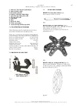
Pousser  le  levier  de  l’inverseur  du  moteur 
autocentrant  (#1  Fig.  14)  vers  la  droite:  l’arbre 
tourne dans le sens des aiguilles d’une montre. 

Pousser  le  levier  de  l’inverseur  du  moteur 

autocentrant (#1 Fig. 14) vers la gauche: l’arbre 
tourne  dans  le  sens  inverse  des  aiguilles  d’une 
montre. 


C.


Actionner le levier de commande du bras porte-
arbre  (# 2 Fig. 14) en position 

:  le bras porte-

arbre se déplace vers le haut. 

Actionner le levier en position 

: le bras porte-arbre 

se déplace vers le bas. 


D.


Actionner  le  levier  de  commande  du  chariot 
porte-outils (# 3 Fig. 14) en position 

A : 

le chariot 

se déplace vers la machine. 

Actionner  le  levier  en  position 

:  le  chariot  se 

déplace vers l’extérieur. 


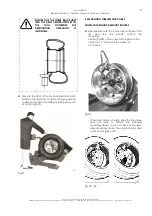
 270 

Fig.14 
 

E.


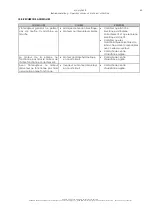
Utiliser  le  levier  de  blocage  (#  1  Fig.  15)  pour 
bloquer et débloquer le bras porte-rouleau. 


                   272 

Fig.15 
 

F.


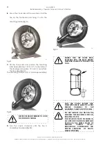
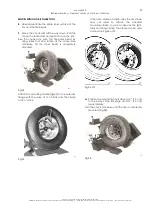
L’arbre  peut  être  bloqué  en  trois  positions 
différentes.  Agir  sur  le  levier  de  blocage  (#1 
Fig.16)  et  faire  coulisser  l’arbre  axialement. 
L’arbre doit être bloqué correctement. 


                     273 

Fig.16 
 

Summary of Contents for monty 3650

Page 1: ...monty 3650 Elektrohydraulische Reifenmontiermaschine Electric Hydraulic Tire Changer Démonte Pneus Électro Hydraulique Betriebsanleitung Operation manual Manuel de l opérateur ...

Page 2: ...harfinde belirtilen teknik dosyay haz rlamaya yetkilidir HUN A szakiIrodaIrodavezetŒjefeljogosította œŸ œE irányelvArészénekVII ellékletébenmeghatározott m szakidokumentációösszeállítására RUS Ž Ž VII A œŸ œCE ITA Direttore Operativo SPA Director Operativo POR Director Operacional ENG Operations anager FRA Directeur Opérationnel DEU Betriebsleiter ALB Drejtori Operativ BUL CES Výkonný editel HRV O...

Page 3: ... в SP DOCUMENTATION SUPPLIED DOCUMENTATION FOURNIE DOCUMENTACIÓN SUMINISTRADA GELIEFERTE DOKUMENTATION DOCUMENTAÇÃO FORNECIDA DOCUMENTAÇÃO FORNECIDA ДОКУМЕНТАЦИИ ПОСТАВЛЯЕМОЙ date of first publication 06 2002 date de la première édition 06 2002 Datum der Erstveröffentlichung 06 2002 data di prima pubblicazione 06 2002 fecha de la primera publicación 06 2002 data da primeira publicação 06 2002 дата ...

Page 4: ...LBOHRUNG Seite 14 5 2 AUFSPANNUNG VON FELGEN MIT 164 MM MITTELBOHRUNG Seite 16 5 3 AUFSPANNUNG VON FELGEN MIT 135 167 MM MITTELBOHRUNG Seite 16 5 4 DEMONTAGE VON LKW SCHLAUCHLOSREIFEN Seite 17 5 5 MONTAGE VON LKW SCHLAUCHLOSREIFEN Seite 18 6 0 WARTUNG Seite 22 7 0 INNERBETRIEBLICHE UMSETZUNG DER MASCHINE Seite 22 8 0 LÄNGFRISTIGE MASCHINENSTILLEGUNG Seite 22 9 0 VERSCHROTTUNG Seite 22 10 0 FEHLERS...

Page 5: ...CESSOIRES D ORIGINE Page 45 1 8 ACCESSOIRES EN OPTION Page 46 1 9 PRÉCAUTIONS GÉNÉRALES Page 47 1 10 DISPOSITIFS DE SÉCURITÉ Page 47 2 0 TRANSPORT Page 48 2 1 DÉBALLAGE Page 48 2 2 LIEU D INSTALLATION Page 48 3 0 MONTAGE ET MISE EN OEUVRE Page 49 3 1 BRANCHEMENT ÉLECTRIQUE Page 50 3 2 CONTROLE DU SENS DE ROTATION MOTEUR Page 50 4 0 COMMANDES Page 51 5 0 MONTAGE ET DÉMONTAGE PNEUS PRÉCAUTIONS GÉNÉR...

Page 6: ...tigen Gebrauch nicht verantwortlich gemacht werden 1 2 ALLGEMEINES Die vorliegende Betriebsanleitung ist Bestandteil des Produktes Lesen Sie die Anweisungen und Warnungen in der vorliegenden Betriebsanleitung genau durch da sie wichtige Hinweise für den sicheren Einsatz und die Wartung dieses Geräts vermitteln 1 3 ALLGEMEINE SICHERHEITSVORSCHRIFTEN DAS GERÄT DARF NUR VON PERSONAL BEDIENT WERDEN DA...

Page 7: ...inengewicht mit Serienzubehör 330 kg 726 Ibs Elektrischer Anschluß 400 VAC 3 50 60 Hz 8 2 A Pumpemmotorleistung 0 75 kW 1 HP Spannfuttermotorleistung 0 75 kW 1 HP Felgendurchmesser 16 22 5 Max Felgenbreite 12 Max Reifendurchmesser 1200 mm 47 Max Reifenbreite 500 mm 20 Max Drehmoment am Spannfutter 1800 Nm 1323 ftxIbs Drehgeschwindigkeit Spannfutter 4 U min Schalldruck 70dBA 1 6 MASCHINENABMESSUNGE...

Page 8: ...flansch und Felge 303 Abb 5 4009472 Montageklemme Abb 6 Zum Zusammenhalten von Wulst und Felge während der Reifenmontage auf Stahlfelgen Zur Verwendungsweise siehe Kap 5 4 295 Abb 6 1 8 ZUBEHÖR AUF ANFRAGE 4015339 Montageklemme für Alu Felgen Abb 7 Zum Zusammenhalten von Wulst und Felge während der Reifenmontage auf Alufelgen Zur Verwendungsweise siehe Kap 5 5 296 Abb 7 4021247 Konusflansch Abb 8 ...

Page 9: ...RTUNGS UND REPARATURARBEITEN AN DER MASCHINE DÜRFEN KEINE KRAVATTEN KETTEN ODER ANDERE LOSE ACCESSOIRES GETRAGEN WERDEN AUCH LANGE HAARE SIND GEFÄHRLICH UND DESHALB ENTSPRECHEND ZU SCHÜTZEN DER BEDIENER MUSS EINE ANGEMESSENE SICHERHEITSAUSRÜSTUNG TRAGEN WIE HANDSCHUHE SICHERHEITSSCHUHE UND SCHUTZBRILLE E ELEKTRISCHE KABEL MÜSSEN IN GUTEM ZUSTAND GEHALTEN WERDEN F DER RADSCHUTZ UND DIE ANDEREN SICH...

Page 10: ...DSCHUHE TRAGEN UM KRATZER UND SCHÜRFUNGEN DURCH DEN KONTAKT MIT DEM VERPACKUNGSMATERIAL ZU VERMEIDEN 2 2 AUFSTELLUNGSORT Die Maschine an einem trockenen und überdachten möglichst geschlossenen Ort aufstellen Für die Aufstellung der Maschine wird eine Nutzfläche von 350x350cm 12 x12 Abb 10 298 Abb 10 Sicherstellen daß der Bediener von der Bedienposition aus das gesamte Gerät und das Umfeld einsehen...

Page 11: ...sbolzen einsetzen und die Sicherungsmutter richtig festziehen Sicherstellen daß die Elektrokabel und Hydraulikschläuche dabei nicht gequetscht oder beschädigt werden Abb 11 299 Abb 11 B Den Zubehörhalter anbringen und mit der entsprechenden Schraube befestigen Abb 11 C Die Schrauben abnehmen mit denen die Maschine an der Palette befestigt ist Die Maschine mit einem ausreichend langen 300 cm und ro...

Page 12: ...s Maschinenkabel einen zugelassenen Stecker anschliessen HINWEIS Bevor das Gerät angeschlossen wird muß eine Elektrofachkraft den Zustand der elektrischen Zufuhrleitung überprüfen HINWEIS Der Schutzleiter hat die Farbe gelb grün Der Schutzleiter darf nie an eine der beiden Phasen angeschlossen werden Sicherstellen daß die Werkstattelektroanlage mit einem Überstromausschalter mit auf 30 mA geeichte...

Page 13: ...DARAUF FOLGENDEN ARBEITSVORGANG LÄNGER ALS 5 MINUTEN IST B Den Wendehebel der Spannfuttermotors 1 Abb 14 nach rechts drehen das Spannfutter dreht sich im Uhrzeigersinn Den Wendehebel der Spannfuttermotors 1 Abb 14 nach links drehen das Spannfutter dreht sich gegen den Uhrzeigersinn C Den Steuerhebel des Spannfutterarms 2 Fig 14 in Position A bewegen der Spannfutterarm bewegt sich nach oben Den Heb...

Page 14: ...N D FÜR EINE KORREKTE REIFENMONTAGE UND REIFENZENTRIERUNG AUF DER FELGE IST EINE AUSREICHENDE SCHMIERUNG UNBEDINGT NOTWENDIG DAZU AUSSCHLIESSLICH EIN SPEZIELLES REIFENSCHMIERMITTEL VERWENDEN E SICHERSTELLEN DASS DER REIFEN MASSLICH ZUR FELGE PASST 5 1 AUFSPANNUNG VON FELGEN MIT 220 UND 280 MM MITTELBOHRUNG A Die bewegliche Plattform nach außen fahren Das Rad auf die Plattform rollen B Das Spannfut...

Page 15: ...ündigung vor _ HOFMANN reserves the right of modification without notice _ Document non contractuel 15 D Das Rad mit dem entsprechenden Flansch auf dem Spannfutter arretieren wobei immer zu prüfen ist daß das Felgentiefbett nach außen zeigt Abb 18 268 Abb 18 E Die Spannfutterwelle in Abhängigkeit von der Lage des Felgenflansches positionieren Abb 19 20 274 Abb 19 275 Abb 20 ...

Page 16: ...0798 gebraucht der als Sonderzubehör auf Anfrage lieferbar ist A Den 220 280mm Flansch wie in Abb 21 gezeigt vom Spannfutter abnehmen 306 Abb 21 B Zum Spannen der Felge den Sternflansch D164 mm verwenden wie in Kap 5 1 beschrieben 5 3 AUFSPANNUNG VON FELGEN MIT 135 167 MM MITTELBOHRUNG Zum Spannen dieses Felgentyps muß der Konusflansch 4021247 verwendet werden der auf Anfrage lieferbar ist A Den D...

Page 17: ...n 281 Abb 25 C Das Spannfutter nach oben oder nach unten fahren sodaß die Abdrückrolle am Felgenhorn anliegt Das Spannfutter gegen den Uhrzeigersinn drehen und gleichzeitig den Werkzeugträgerschlitten in kurzen Abständen nach innen bewegen um den Reifen abzudrücken Das Spannfutter weiterdrehen und dabei Felge und Reifenwulst mit dem entsprechenden Schmiermittel großzügig schmieren NUR SPEZIELLE RE...

Page 18: ...ontage mit beiden Händen festhalten um zu verhindern daß der Reifen herunterfällt oder unkontrolliert wegrollt Abb 27 283 Abb 27 5 5 MONTAGE VON LKW SCHLAUCHLOSREIFEN MODELL MIT MONTAGE DEMONTAGEROLLEN A Die ganze Innenfläche der Felge und die Reifenwülste großzügig schmieren Die Montageklemme am Felgenaußenrand anbringen Abb 28 wobei das Ventil in 11 Uhr Position und die Klemme in 12 Uhr Position...

Page 19: ... cm vom Felgenhorn freisteht Abb 32 Die Montageklemme befindet sich in 11 Uhr Stellung 286 Abb 32 NIE DIE HÄNDE VERWENDEN UM DEN REIFEN AUF DER FELGE ZU HALTEN D Das Spannfutter im Uhrzeigersinn soweit drehen bis der Reifen vollständig montiert ist Abb 33 288 Abb 33 SICHERSTELLEN DASS DER ÄUSSERE WULST SICH INS TIEFBETT SCHIEBT WENN SICH DIE MONTAGEKLEMME GENAU GEGENÜBER VOM WERKZEUG BEFINDET 279 ...

Page 20: ...en und gleichzeitig das Spannfutter im Uhzeigersinn drehen bis der innere Wulst aufgezogen ist 828 Abb 34 G Die Montageklemme am Felgenaußenrand anbringen Abb 35 wobei das Ventil in 11 Uhr Position und die Klemme in 12 Uhr Position stehen muß 286 Abb 35 H Handelt es sich um eine ALU Felge könnte die Form des Felgenhorns das Anbringen einer Standardmontageklemme unmöglich machen In diesem Fall ist ...

Page 21: ...RFOLGEN DA DIESE NICHT DAFÜR BESTIMMT IST ZUM REIFENFÜLLEN DEN REIFEN IN EINEN ZULÄSSIGEN FÜLLKÄFIG ÜBERSTELLEN WICHTIGER HINWEIS DIE BEIDEN WÜLSTE KÖNNEN NICHT GLEICHZEITIG MIT DEM MONTAGEFINGER MONTIERT WERDEN 6 0 WARTUNG VOR ALLEN WARTUNGSARBEITEN MUSS SICHERGESTELLT WERDEN DASS KEINE RÄDER AUF DEM SPANNFUTTER GESPANNT SIND UND DASS DIE STROMZUFUHR DES GERÄTS ABGESCHALTET IST A Alle Stellen mit...

Page 22: ...cht mehr eingesetzt werden wird die sofortige Stillegung durch Entfernung des Anschlußkabels empfohlen Setzen Sie sich zur Verschrottung des Geräts am Ende seiner Lebensdauer bitte mit Ihrem Händler in Verbindung und fragen Sie ihn nach einem Preisangebot bzw nach den Bestimmungen zur Entsorgung des Geräts Dieses Symbol zeigt an dass es Pflicht ist elektrische und elektronische Geräte nach der Ver...

Page 23: ...ng fehlt Motoren oder Schalter durchgebrannt Kontrollieren ob der Stecker korrekt eingesteckt ist und ob die Stromzufuhr funktioniert Kontrollieren ob die elektrischen Anforderungen des Geräts mit den Merkmalen der Werkstatt anlage vereinbar sind Den Kundendienst rufen Der Pumpenmotor funktioniert nicht während der Spannfuttermotor einwandfrei arbeitet Kurzschluß im Motor der Hydrauliksteuerung De...

Page 24: ... s Manual Notice d utilisation Modéle monty 3650_ DE EN FR_ Release December 2018 HOFMANN behält sich das Recht zu Änderungen ohne Vorankündigung vor _ HOFMANN reserves the right of modification without notice _ Document non contractuel 24 ...

Page 25: ...ered liable for possible damages caused by improper wrong or non reasonable use 1 2 NOTICE This manual is a part of the product Read carefully the warnings and instructions of this manual since they provide important information concerning safety and maintenance 1 3 GENERAL SAFETY INSTRUCTIONS THE USE OF THIS DEVICE IS ALLOWED ONLY TO PERSONNEL DULY TRAINED BY AN AUTHORIZED HOFMANN DEALER ANY MISU...

Page 26: ... with standard acc 330 kg 726 lbs Electric specifications 400VAC 3ph 50 60Hz 8 2A Hydraulic motor power 0 75 kW 1 HP Chuck rotation motor power 0 75 kW 1 HP Rim diameter range 16 22 5 Max rim width 12 Max tire diameter 1200 mm 47 Max tire width 500 mm 20 Max chuck torque 1800 Nm 1323 ftxlbs Chuck rotation speed 4 rpm Acoustic pressure 70dBA 1 6 DIMENSIONS OF THE MACHINE Fig 2 1 7 STANDARD ACCESSOR...

Page 27: ...Fig 5 To lock star flange and rim in place 303 Fig 5 4009472 Mounting clamp Fig 6 To hold the bead when mounting tires on steel rims Description on use is in section 5 4 Fig 6 1 8 ACCESSORIES ON REQUEST 4015339 Clamp for ligth alloy rims Fig 7 To hold the bead when mounting tires on light alloy rims Description on use is in section 5 5 296 Fig 7 4021247 Cone flange Fig 8 To center and hold rims wi...

Page 28: ...OF THE POWER SOURCE C BEFORE ANY MAINTENANCE OR REPAIRS ARE ACCOMPLISHED THE MACHINE MUST BE DISCONNECTED FROM THE ELECTRIC SUPPLY D NEVER WEAR TIES CHAINS OR OTHER LOOSE ARTICLES WHEN USING MAINTAINING OR REPAIRING THE MACHINE LONG HAIR IS ALSO DANGEROUS AND SHOULD BE KEPT UNDER A HAT THE USER MUST WEAR PROPER SAFETY ATTIRE IE GLOVES SAFETY SHOES AND GLASSES E MAINTAIN ALL ELECTRIC CORDS IN GOOD ...

Page 29: ...CRATING THE MACHINE TO PREVENT SCRATCHES OR ABRASIONS DUE TO THE CONTACT WITH PACKING MATERIALS 2 2 INSTALLATION AREA Install the machine in a covered and dry area The installation of the machine requires a free space of at least cm 350x350 12 x12 Fig 10 298 Fig 10 Make sure that from the operating position the user can see all of the machine and the surrounding area The operator shall forbid in s...

Page 30: ... A Move the control arm to a vertical position Install the lock bolt and tighten the nut properly Make sure that the electric cable and hydraulic hoses are not caught nor damaged Fig 11 299 Fig 11 B Install the accessories peg and lock with screw Fig 11 C Remove the screws that secure the machine to the pallet Lift the machine with a belt or a rope of appropriate strength and length 300 cm 10 Fig ...

Page 31: ... system Connect the electric cable of the machine with an approved plug NOTE The outlet installation must be verified by a licensed electrician before connecting the tire changer NOTE The yellow with green wire in the cord is the grounding wire Never connect the grounding wire to a live terminal Check that the power supply has an automatic circuit breaker with a differential circuit set at 30 mA T...

Page 32: ...G OR DEMOUNTING OPERATION IF THE TIME BEFORE THE NEXT OPERATION IS LONGER THAN 5 MINUTES B Operate the chuck rotation switch 1 Fig 14 to the right the chuck rotates clockwise Operate the chuck rotation switch to the left the chuck rotates counter clockwise C Operate the chuck arm control 2 Fig 14 to position A the chuck arm moves upwards Operate the control to position B the chuck arm moves downwa...

Page 33: ...VE STEM IS MADE OF METAL D LUBRICATION IS NECESSARY TO MOUNT THE TIRE CORRECTLY AND GET A PROPER CENTERING BE SURE YOU ARE USING APPROVED LUBRICANT ONLY E MAKE SURE THE TIRE IS THE CORRECT SIZE FOR THE RIM 5 1 LOCKING RIMS WITH A CENTER HOLE OF 220MM AND 280MM A Move the footboard all the way to the outside Roll the wheel onto the footboard B Move the chuck approximately to the center of the rim M...

Page 34: ...ankündigung vor _ HOFMANN reserves the right of modification without notice _ Document non contractuel 34 D Lock the wheel to the chuck with the appropriate flange checking that the drop center of the rim is towards the outside of the machine Fig 18 268 Fig 18 E Position the shaft of the machine depending on the position of the rim flange Fig 19 20 274 Fig 19 275 Fig 20 ...

Page 35: ...this type of rims it is required the appropriate star flange 4020798 supplied on demand A Remove the 280mm flange from the chuck as shown in Fig 21 306 Fig 21 B Lock the rim with the 164mm star flange as described in section 5 1 5 3 LOCKING RIMS WITH A CENTER HOLE OF 135 167 MM To lock this type of rims it is required the cone flange 4021247 supplied on demand A Mount the spacer ring onto the chuc...

Page 36: ... Fig 25 281 Fig 25 C Lift or lower the chuck so that the bead breaker roller remains close to the rim edge Turn the chuck counter clockwise and at the same time move the toolholder carriage step by step towards the inside to break the bead Continue to turn the chuck and lubricate the bead and the rim liberally with an approved lubricant USE ONLY SPECIFIC LUBRICANTS FOR TIRES AND WHEELS APPROVED LU...

Page 37: ...ire and hold it with both hands in the last part of demounting operation to prevent the tire from falling or rolling away out of control Fig 27 283 Fig 27 5 5 MOUNTING TUBELESS TRUCK TIRES MODEL WITH MOUNT DEMOUNT ROLLERS A Liberally lubricate the entire inner surface of the rim and the tire beads Attach the mounting clamp Fig 28 to the outer rim flange with the valve at 11 o clock and the clamp a...

Page 38: ...ox 1 5 cm away from the rim edge Fig 32 The mounting clamp is at 11 o clock approximately 288 Fig 32 NEVER USE HAND PRESSURE TO HOLD THE TIRE ONTO THE RIM D Turn the chuck clockwise until the tire is completely mounted Fig 33 289 Fig 33 ENSURE THAT THE OUTER BEAD DESCENDS INTO THE DROP CENTER WHEN THE CLAMP IS OPPOSITE TO THE TOOL 279 STOP THE CHUCK BEFORE ONE COMPLETE TURN IS MADE TO AVOID SERIOU...

Page 39: ... Rise the chuck arm push the tire outer bead by using roller tool and rotate at the same time clockwise till the inner bead is completely mounted 828 Fig 34 Attach the mounting clamp Fig 35 to the outer rim flange with the valve at 11 o clock and the clamp at 12 o clock 286 Fig 35 If the rim is made of a ligth alloy the rim shape may not allow to attach the standard mounting clamp In such a case u...

Page 40: ...NOT INFLATE THE TIRE ON THE MACHINE THIS MACHINE IS NOT AN INFLATION DEVICE FOR INFLATION PLACE THE WHEEL IN AN APPROVED INFLATION RESTRAINT DEVICE IN THE UNITED STATES OF AMERICA CONSULT O S H A REGULATIONS CONCERNING THE PROPER SERVICING OF TRUCK WHEELS AND RIMS IMPORTANT IT IS NOT POSSIBLE TO MOUNT TWO BEADS AT A TIME USING THE HOOK TOOL 6 0 MAINTENANCE BEFORE STARTING ANY MAINTENANCE OPERATION...

Page 41: ... of all previously protected parts and check for correct functioning of all devices before using the machine again 9 0 SCRAPPING THE MACHINE Once it is decided to no longer use this machine it is required to make it inoperable by cutting the electric cord To dispose of the equipment at the end of its life contact the reseller for a quote or for the regulations on disposal which apply to the unit T...

Page 42: ...hine does not work No electric power Switch or motors burnt Check that the electric plug is correctly fitted to the socket and that the electric power is on Check that the electric requirements of the machine are the same as the supply Call the authorized service center for assistance Pump motor does not turn but the chuck motor is operated normally Hydraulic motor burnt Call the authorized servic...

Page 43: ... s Manual Notice d utilisation Modéle monty 3650 _DE EN FR_ Release December 2018 HOFMANN behält sich das Recht zu Änderungen ohne Vorankündigung vor _ HOFMANN reserves the right of modification without notice _ Document non contractuel 43 ...

Page 44: ...nés 1 2 GÉNÉRALITÉS Ce manuel fait partie intégrante du produit Lire attentivement les instructions et les notices explicatives contenues dans ce manuel puisqu elles donnent des indications importantes pour ce qui concerne la sécurité d emploi et l entretien 1 3 RÈGLES GÉNÉRALES DE SÉCURITÉ L EMPLOI DE L APPAREIL EST PERMIS SEULEMENT AU PERSONNEL OPPORTUNÉMENT FORMÉ PAR LE DISTRIBUTEUR AUTORISÉ HO...

Page 45: ...c accessoires en dotation 330 kg 726 lbs Caractéristiques électriques 400VAC3 50 60Hz 8 2A Puissance moteur pompe 0 75 kW 1 HP Puissance moteur arbre 0 75 kW 1 HP Diamètre jante 16 22 5 Largeur maxi jante 12 Diamètre maxi pneu 1200 mm 47 Largeur maxi pneu 500 mm 20 Couple maximum à l arbre 1800 Nm 1323ftxlbs 19 Vitesse rotation arbre 4 t min Emission acoustique 70dBA 1 6 DIMENSIONS DE LA MACHINE 2...

Page 46: ...e montage Fig 6 Pour retenir le talon pendant le montage de pneus sur jantes en acier Les instructions pour l emploi sont décrites au paragraphe 5 4 295 Fig 6 1 8 ACCESSOIRES EN OPTION 4015339 Etau pour roues en tôle légère Fig 7 Pour retenir le talon contre la jante pendant le montage de pneus sur jantes en tôle légère Les instructions pour l emploi sont décrites au paragraphe 5 5 296 Fig 7 40212...

Page 47: ...JAMAIS DE CRAVATES DE CHAÎNES OU AUTRES LORSQUE L ON EXÉCUTE DES OPÉRATIONS D EMPLOI D ENTRETIEN OU DE RÉPARATION SUR LA MACHINE LES CHEVEUX LONGS SONT ÉGALEMENT DANGEREUX ILS DOIVENT ÊTRE RASSEMBLÉS SOUS UNE CASQUETTE OU AUTRE L OPÉRATEUR DOIT PORTER DES VÊTEMENTS ADÉQUATS DES GANTS DES CHAUSSURES DE SÉCURITÉ ET DES LUNETTES E LES CÂBLES ÉLECTRIQUES DOIVENT ÊTRE CONSERVÉS EN BON ÉTAT F LE CARTER ...

Page 48: ...iner selon les règles locales en vigueur PORTER TOUJOURS LES GANTS PENDANT LE DÉBALLAGE POUR ÉVITER DES GRIFFURES OU DES ÉGRATIGNURES DUES AU CONTACT AVEC LE MATÉRIEL DE L EMBALLAGE 2 2 LIEU D INSTALLATION Installer la machine dans un lieu couvert sec et si possible clos L installation de la machine nécessite un espace utile d au moins 350x350 cm 12 x12 Fig 10 298 Fig 10 S assurer que l opérateur ...

Page 49: ...tion verticale Introduire le boulon de fixation et serrer l écrou de façon appropriée S assurer que le câble électrique et les tuyaux hydrauliques ne soient pas écrasés ni endommagés Fig 11 299 Fig 11 B Monter le support accessoires et le fixer avec la vis Fig 11 C Enlever les vis qui fixent la machine à la palette Soulever la machine avec une lanière ou une corde de robustesse et longueur appropr...

Page 50: ...ble électrique de la machine à une fiche homologuée REMARQUE L installation électrique de distribution doit être vérifiée par un électricien avant de relier l équilibreuse REMARQUE Le câble de terre est jaune vert Ne jamais relier le câble de terre à l une des phases Contrôler si l installation de distribution est pourvue d un dispositif d interruption automatique contre les surintensités équipé d...

Page 51: ...TION SUCCESSIVE EST SUPÉRIEUR A 5 MINUTES B Pousser le levier de l inverseur du moteur autocentrant 1 Fig 14 vers la droite l arbre tourne dans le sens des aiguilles d une montre Pousser le levier de l inverseur du moteur autocentrant 1 Fig 14 vers la gauche l arbre tourne dans le sens inverse des aiguilles d une montre C Actionner le levier de commande du bras porte arbre 2 Fig 14 en position A l...

Page 52: ... D LE GRAISSAGE EST NÉCESSAIRE POUR MONTER CORRECTEMENT LE PNEU ET OBTENIR UN CENTRAGE CORRECT DE LA BANDELETTE UTILISER EXCLUSIVEMENT DU LUBRIFIANT SPÉCIFIQUE POUR PNEUS E CONTRÔLER QUE LE PNEU SOIT DE LA JUSTE DIMENSION POUR LA JANTE 5 1 BLOCAGE DE JANTES AVEC ALÉSAGE CENTRAL DE DIAMÈTRE 220 MM ET 280 MM A Déplacer la plate forme mobile vers l extérieur Placer la roue sur la plate forme B Positi...

Page 53: ...ne Vorankündigung vor _ HOFMANN reserves the right of modification without notice _ Document non contractuel 53 D Bloquer la roue sur l arbre au moyen de la bride spéciale en vérifiant que le canal de la jante soit tourné vers l extérieur de la machine Fig 18 268 Fig 18 E Positionner l arbre selon la position de la bride de la jante Fig 19 20 274 Fig 19 275 Fig 20 ...

Page 54: ...nécessaire d utiliser la bride spéciale en croix 4020798 fournie en option A Démonter la bride 220 280mm de l arbre comme indiqué sur la figure Fig 21 306 Fig 21 B Bloquer la jante en utilisant la bride en étoile d 164 mm comme décrit au 5 1 5 3 BLOCAGE DE JANTES AVEC AÉSAGE CENTRAL DE DIAMÈTRE 135 167 MM Pour bloquer ces types de jante il est nécessaire d utiliser la bride à cône 4021247 fournie ...

Page 55: ...e façon à ce que le détalonneur soit au bord de la jante Tourner l arbre dans le sens inverse des aiguilles d une montre et simultanément déplacer le chariot porte outils à de brefs intervalles vers l intérieur pour détalonner le pneu Continuer à tourner l arbre en graissant abondamment avec du lubrifiant spécial la jante et le talon UTILISER EXCLUSIVEMENT DES LUBRIFIANTS SPÉCIFIQUES POUR PNEUS LE...

Page 56: ...face au pneu et le retenir des deux mains dans la phase finale du démontage pour éviter qu il ne tombe ou ne roule de façon incontrôlée Fig 27 283 Fig 27 5 5 MONTAGE DE PNEUS TUBELESS POUR CAMION MODÈLE AVEC ROULEAUX MONTAGE DÉMONTAGE A Graisser abondamment toute la surface intérieure de la jante et les talons du pneu Fixer l étau de montage Fig 28 au bord extérieur de la jante avec la valve à 11 ...

Page 57: ...à l intérieur du bord de la jante et environ à 1 5 cm en direction radiale Fig 32 L étau de montage se trouve à 11 heures 288 Fig 32 NE JAMAIS RETENIR LE PNEU SUR LA JANTE AVEC LES MAINS D Tourner l arbre dans le sens des aiguilles d une montre jusqu à ce que le pneu ne soit complètement monté Fig 33 289 Fig 33 VÉRIFIER QUE LE TALON EXTÉRIEUR DESCENTE DANS LE CANAL LORSQUE L ÉTAU EST DIAMÉTRALEMEN...

Page 58: ...ilisant le rouleau et au même temps tourner le mandrin dans la direction des aiguilles d une montre jusqu àu montage complet du talon intérieur 828 Fig 34 G Fixer l étau de montage Fig 35 au bord extérieur de la jante avec la valve à 11 heures et l étau à 12 heures 286 Fig 35 Si la jante est en tôle légère la forme du bord pourrait empêcher de fixer l étau standard Dans ce cas utiliser l étau pour...

Page 59: ...DERNIÈRE N EST PAS UN DISPOSITIF DE GONFLAGE POUR GONFLER LE PNEU PLACER LA ROUE EN CAGE DE GONFLAGE HOMOLOGUÉE IMPORTANT IL N EST PAS POSSIBLE DE MONTER LES DEUX TALONS À LA FOIS AVECLE BEC 6 0 ENTRETIEN AVANT TOUTE OPÉRATION D ENTRETIEN OU DE RÉPARATION VÉRIFIER L ABSENCE DE ROUES MONTÉES SUR L ARBRE ET LE DÉBRANCHEMENT DE LA MACHINE DU SECTEUR A Graisser tous les points dotés de graisseur une f...

Page 60: ...N Si l on décide de ne plus utiliser la machine on recommande de la rendre inopérante en coupant le câble électrique Pour la mise à la décharge de l équipement arrivé en fin de vie contacter le revendeur pour une offre ou pour connaître les instructions utiles à son démantèlement Ce symbole indique l obligation d effectuer le tri sélectif des appareils électriques et électroniques au moment de sa ...

Page 61: ... Moteurs ou interrupteurs brûlés Contrôler que la fiche électrique soit insérée correctement et que le réseau électrique soit actif Contrôler que les caractéristiques électriqes de la machine soient compatibles avec celles du secteur Contacter le centre d assistance agréé Le moteur de la pompe ne fonctionne pas mais le moteur de l arbre fonctionne correctement Moteur centrale hydraulique en court ...

Page 62: ...62 ...

Page 63: ... s Manual Notice d utilisation Modéle monty 3650_DE EN FR_ Release December 2018 HOFMANN behält sich das Recht zu Änderungen ohne Vorankündigung vor _ HOFMANN reserves the right of modification without notice _ Document non contractuel 63 ...

Page 64: ...siasi responsabilità per eventuali errori ivi contenuti o per danni accidentali o danni indiretti connessi alla fornitura alle prestazioni o all uso dei presenti materiali Snap on Equipment SrL Manufacturing Facility Via Per Carpi 33 42015 Correggio RE Italy www snapon equipment eu Technical alterations reserved SOE digital code OM_HOF MONTY 3650_18 12_DE EN FR_D1_ZEEWH704A03 ...

Reviews: