
SETTING THE ADDRESS
・
Each sensor must have it’s address set before system operation.
・
Using the installation plan which shows the proper location for each sensor, find the address for the sensor to be installed.
Ensure that the address and location on the plan match correctly.
・
Address is set to 127,when shipping from a factory.
・
For address setting, use the address programmer and write the number on the label of the sensor after setting.
・
Address must be set within the address setting range of the connected panel.
・
When address changing, renew the number on the label.
・
See the instruction manual of the Hand Held programmer(TCH-B100/TCH-B200) about detail of setting method.
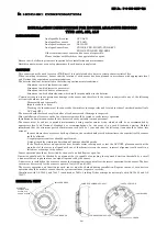
WIRING
The wiring diagram for the analogue sensor base should be made as shown in Fig. 2.
Fig.2
HOW TO USE OF SENSOR HEAD REMOVER
1) In case of sensor head mounting to the base.
a) Adjust the remover for sensor sizes.
b) Grip sensor and push
the sensor to the sensor base softly.
c) Twist clockwise for secure fitting of the sensor head and base.
2) In case of sensor removal from the base.
a) Adjust the remover for sensor sizes.
b) Grip sensor, twist counterclockwise and pull down for removal of the sensor head from the base.
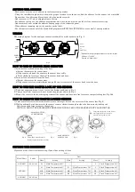
HOW TO USE THE TAMPER LOCK OF THE SENSOR
1) Take any sensor and turn it over to view the bottom as shown in Fig. 3.
2) Using a small slot type screw driver break the prong as shown in Fig. 4.
3) Mount the sensor to the base bringing seams of the sensor and base into line for secure tamper locking (see Fig. 5).
HOW TO REMOVE THE TAMPER LOCKED SENSOR
1) Take a small slot screw driver and insert it into the larger hole on the outer rim of the sensor (see Fig. 6).
2) While pushing the tab down rotate the sensor counter clockwise enough to clear the base security locking tab.
Only use enough force to remove the sensor.
CAUTION: DO NOT USE EXCESSIVE FORCE WHEN UNLOCKING THE BASE SECURITY LOCKING TAB
SETTING THE SENSITIVITY
Please use mode of built in class setting, if panel has setting of class.
Table.1
Model Name
Smoke
Heat
Class
Setting
Class
Setting
Class
Setting
ACC-ASN 2.0-4.5%/m A1 Fixed Temperature 60
℃
- - C
Fixed Temperature 88
℃
ATJ-ASN
-
A1
Fixed Temperature 60
℃
B
Fixed Temperature 78
℃
C
Fixed Temperature 88
℃
A1R
Fixed Temperature 60
℃
BR
Fixed Temperature 78
℃
CR
Fixed Temperature 88
℃
A1S
Fixed Temperature 60
℃
BS
Fixed Temperature 78
℃
CS
Fixed Temperature 88
℃
ALN-ASN 2.0-4.5%/m
-
SMALL SLOT TYPE
SCREW DRIVER
PRONG
This will prevent the sensor
from being removed from the base
BASE SECURITY
LOCKING TAB
Insert small slot type screw driver
into larger hole in a sensor to
release locking tab on base
Fig.3 Fig.4
Fig.5
Fig.6
*Optional wiring configurations for remote output
Voltage: 17 to 40V
Current: 8.0mA±20%
LOOP
OUT
POWER
LINE
PANEL
Next
Sensor
to
LOOP IN


