

- 3 -
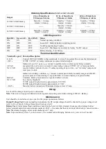
Stand-by Specifications
(total current shown)
:
Output
4 hr. of Stand-by &
5 Minutes of Alarm
24 hr. of Stand-by &
5 Minutes of Alarm
60 hr. of Stand-by &
5 Minutes of Alarm
12VDC / 40AH Battery
Stand-by = 6.0 amp
Alarm = 6.0 amp
Stand-by = 1.0 amp
Alarm = 6.0 amp
Stand-by = 300mA
Alarm = 6.0 amp
24VDC / 12AH Battery
--------
Stand-by = 200mA
Alarm = 6.0 amp
--------
24VDC / 40AH Battery
Stand-by = 6.0 amp
Alarm = 6.0 amp
Stand-by = 1.0 amp
Alarm = 6.0 amp
Stand-by = 300mA
Alarm = 6.0 amp
LED Diagnostics:
Red (DC) Green (AC) Red (BAT) Status
ON
ON
ON
Normal operating condition.
ON
OFF
ON
Loss of AC. Stand-by battery supplying power.
OFF
ON
OFF
No DC output. Battery Trouble
OFF
OFF
OFF
Loss of AC. Discharged or no stand-by battery. No DC output.
ON
ON
OFF
Battery missing / Low battery.
Terminal Identification:
Terminal Legend Function/Description
L, G, N
Connect 220VAC 50/60Hz to these terminals: L to hot, N to neutral. Do not use the [G] terminal.
+ DC ---
12VDC / 24VDC @ 6 amp continuous non power-limited output.
AC Fail
NC, C, NO
Indicates loss of AC power, e.g. connect to audible device or alarm panel. Relay normally
energized when AC power is present. Contact rating 1 amp @ 28VDC. AC or brownout fail is
reported within 1 minute of event. To delay reporting of up to 6 hrs., cut “AC delay” jumper and
reset power to unit.
Bat Fail
NC, C, NO
Indicates low battery condition, e.g. connect to alarm panel. Relay normally energized when DC
power is present. Contact rating 1 amp @ 28VDC. A removed battery is reported within
5 minutes. Battery reconnection is reported within 1 minute.
Low battery threshold:
12VDC output threshold set @ approximately 10.5VDC,
24VDC output threshold set @ approximately 21VDC.
+ BAT ---
Stand-by battery connections. Maximum charge current 0.7 amp.
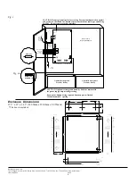
Use 14 AWG or larger for all power connections.
Wiring:
Note:
Take care to keep power-limited circuits separate from non power-limited wiring (220VAC, Battery).
Maintenance:
Unit should be tested at least once a year for the proper operation as follows:
Output Voltage Test:
Under normal load conditions, the DC output voltage should be checked for proper voltage level
(
refer to Power Supply Voltage Output Specifications chart
).
Battery Test:
Under normal load conditions check that the battery is fully charged, check specified voltage both at
battery terminal and at the board terminals marked [+ BAT ---] to ensure that there is no break in the battery connection wires.
Note:
Maximum charging current under discharge is 0.7 amp.
Note:
Expected battery life is 5 years, however, it is recommended changing batteries in 4 years or less if needed.