
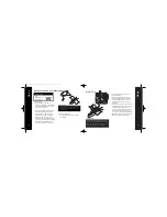
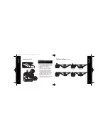

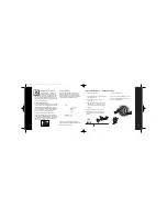
Step 2
5
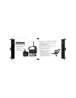
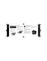
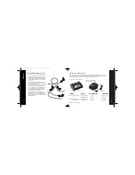
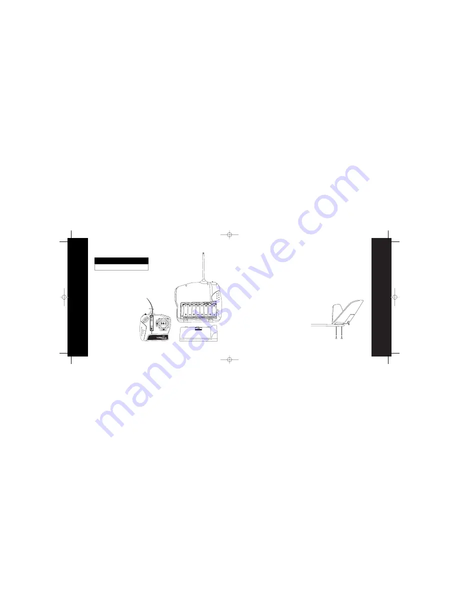
Step 1
4
1. Remove the transmitter back cover by pushing down
with your thumbs, as indicated.
2. Install the included “AA” batteries according to the
diagram in the battery compartment.
3. Replace the cover.
4. To test, switch on the transmitter—the LED should
glow brightly.
5. Replace the batteries when you hear
the low-battery alarm (beeping sound).
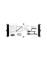
Needed for Step 1
8 "AA" Batteries (included)
Transmitter
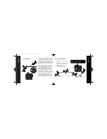
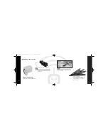
Attaching the Tail
Your Aerobird Xtreme™ comes nearly ready to fly. You
simply need to attach the tail, wing, and landing gear
prior to flight.
To attach the tail:
1. Locate the fuselage and carefully remove from the packing carton. Use caution when removing the fuse-
lage. (Note: The tail is not mounted on the fuselage, but the control lines that exit the fuselage are
attached to the control surfaces of the tail).
2. Locate the two included screws that will mount the tail to the tail boom.
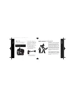
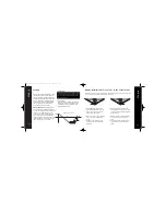
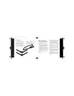
3.
Be sure lines are not twisted
and hold the tail in place.
4. Secure the tail as shown in diagram (a) using the two screws. Attach rubber bands on bottom of tail as
shown.
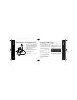
5. Turn on the transmitter and install the fully charged flight battery pack.
6. Make certain the control stick and trim levers on the transmitter are centered as shown in the diagram
on page 10.
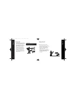
7. With the radio system on and the transmitter stick at neutral, both tail
control surfaces should be level with the rest of the tail.
8. Give transmitter input. The control surfaces should react as illustrated
in the diagrams on page 11.
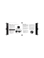
9. If you find that the control surfaces are not functioning properly (ie. too
much slack in the line, not level with the tail in neutral position) DO
NOT FLY. Instead, perform the following procedure:
a. Turn the transmitter on, plug in flight battery and center the right
control stick and trim levers.
b. Use your fingers or a small flat screwdriver to turn the slotted spool
on the control horn. Depending upon which direction you turn the
spool, this will lengthen or shorten the control line.
c. While applying some tension to the control line, adjust until the
control surfaces are level with the rest of the surface.
d. If the control surfaces react the exact opposite as shown in the dia-
gram on page 11, the lines have been reversed and will need to be
corrected.
a.
5723_HBZ Aerobird X manual 12/15/03 1:55 PM Page 4


