background image


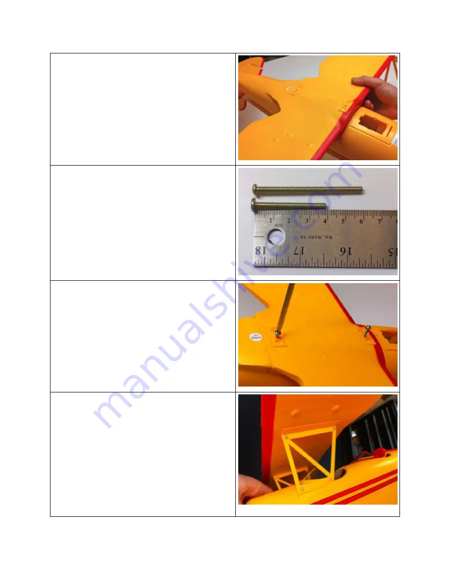
22. Place the lower wing into position on the 

fuselage making sure to not pinch any 
wires in the wing saddle. 


23. The wing mounting screws are 40mm and 

60mm long.  

24. Use the 40mm long screw at the rear of 

the wing and the 60mm screw at the front 
of the wing. Snug up but do not over 
tighten. 

25. Place the upper wing into position on the 

fuselage cabane struts and screw into 
position using 2-8mm long screws on 
each.  


Summary of Contents for ESM1100

Page 1: ...r If you are not already experienced with radio controlled models we strongly suggest that you find an experienced modeler to assist you Warranty Hobby Lobby guarantees this kit to be free from defects in both material and workmanship at the date of purchase This warranty does not cover any component parts damaged by use or modification In no event shall Hobby Lobby s liability exceed the original...

Page 2: ...painted Wings with Scale Rib Detail and Corrugated Ailerons Wing N Struts and Fuselage Cabanes Pre painted Vertical Tail Pre painted Horizontal Tail Pushrods pre installed 4 Channel 72mHz Transmitter and 72mHz Receiver pre installed 3 Cell 1500mAh LiPoly Battery Brushless Outrunner Motor Brushless Controller LiPoly Balance Charger Scale Propeller with Spinner Miscellaneous Hardware Additional Item...

Page 3: ...mm long screws for fuselage cabanes horizontal tail vertical tail 4 Eight 5mm long screws for outer wing N struts 5 Two 5mm screws for spinner 6 Locate the pre painted fuselage 7 You will use 4 8mm long screws for the tail assembly 8 Locate horizontal tail the plastic bracket and 2 8mm screws ...

Page 4: ... bracket with 2 8mm screws 11 Locate the vertical tail Slide the wire from the tailwheel into the plastic mount on the bottom of the rudder 12 Slide the vertical fin into position in the mount on top of the horizontal tail Tab at front of tail inserts into fuselage Screw the fin and rudder into position using 2 8mm long screws 13 Place the N strut into position on the bracket in the lower wing ...

Page 5: ...ts are screwed in place on the fuselage side of the strut brackets 16 Cabane struts are the struts that mount onto the fuselage They are screwed into position using 8mm long screws 17 Position the cabane struts on their proper sides they are each marked as either left or right Please note that the cabane struts mount on the outside of the strut brackets ...

Page 6: ...screws 19 Cabane struts mounted and awaiting the installation of the upper wing panel 20 The receiver is pre installed and pre connected to the elevator and rudder servos The open extension is for the ailerons 21 Plug the aileron servo into the open servo extension ...

Page 7: ...ddle 23 The wing mounting screws are 40mm and 60mm long 24 Use the 40mm long screw at the rear of the wing and the 60mm screw at the front of the wing Snug up but do not over tighten 25 Place the upper wing into position on the fuselage cabane struts and screw into position using 2 8mm long screws on each ...

Page 8: ...f the aileron inter connector pushrod as shown in the photo 28 Attach the clevis end to the upper aileron You may need to adjust the length of the pushrod so that both of the ailerons are in neutral position at the same time 29 Snap the wire landing gear into the slot at the front of the battery box area ...

Page 9: ...the charged battery into position through the battery hatch Slide the battery forward in the battery slot 32 View of the battery access with the flight battery installed Notice that the battery is slid all the way forward in the battery box for proper CG location 33 Replace the battery hatch ...

Page 10: ... the part with the internal posts face down on the bench Fit each prop blade onto the posts The larger hole is on the front side of the blade 37 Fit the back side of the hub into position and secure with 2 12mm long screws 38 Slip the prop into position on the prop adapter with the mounting screws facing the rear ...

Page 11: ...ning the mounting nut make sure to orient the small holes on the sides of the transparent part at 90 degrees to the prop blade orientation 42 Slip the spinner into position and check that the small pilot holes in the spinner match the holes in the transparent part A fine piece of music wire or a pin are helpful for this 43 2 5mm screws will hold the spinner in position ...

Page 12: ... the leading edge of the upper wing It is set at approx 3 back from the LE 47 Check that the control surfaces are at neutral 48 With the trim adjustments on the transmitter in their middle position the control surfaces on the model should be neutral 49 Adjust the length of the pushrods as necessary 50 The control throws should be approximately 51 Elevator 5 8 Up and Down ...

Page 13: ...ons 1 2 Up and Down 53 Rudder 1 1 8 Each Way Hobby Lobby International Inc 5614 Franklin Pike Circle Brentwood TN 37027 1 866 WE FLY RC 1 866 933 5972 www hobby lobby com PEL4107 V2 Instruction Manual doc 6 10 mgh ...

Reviews: