background image

OM-244 013 Page 6

D

Assurez


vous que le fil de terre du cordon d’alimentation est cor-

rectement relié à la borne de terre dans la boîte de coupure ou que
la fiche du cordon est branchée à une prise correctement mise à la
terre 


 vous devez toujours vérifier la mise à la terre.

D

Avant d’effectuer les connexions d’alimentation, vous devez relier
le bon fil de terre.

D

Les câbles doivent être exempts d’humidité, d’huile et de graisse;
protégez


les contre les étincelles et les pièces métalliques chau-

des.

D

Vérifiez fréquemment le cordon d’alimentation afin de vous assurer
qu’il n’est pas altéré ou à nu, remplacez


le immédiatement s’il l’est.

Un fil à nu peut entraîner la mort.

D

L’équipement doit être hors tension lorsqu’il n’est pas utilisé.

D

Vérifiez et remplacez les cosses du câble du chalumeau si elles
sont usées ou altérées.

D

Le câble du chalumeau ne doit pas s’enrouler autour de votre
corps.

D

Si les normes le stipulent, la pièce à couper doit être mise à la terre.

D

Utilisez uniquement de l’équipement en bonne condition. Réparez
ou remplacez immédiatement toute pièce altérée.

D

Portez un harnais de sécurité si vous devez travailler au


dessus

du sol.

D

Assurez


vous que tous les panneaux et couvercles sont correcte-

ment en place.

D

N’essayez pas d’aller à l’encontre des systèmes de verrrouillage
de sécurité ou de les contourner.

D

Utilisez uniquement le ou les chalumeaux recommandés dans le
manuel de l’opérateur.

D

N’approchez pas le tube du chalumeau et l’arc pilote lorsque la gâ-
chette est enfoncée.

D

Le câble de masse doit être pincé correctement sur la pièce à cou-
per,  métal  contre  métal  (et  non  de  telle  sorte  qu’il  puisse  se
détacher), ou sur la table de travail le plus près possible de la ligne
de coupage.

D

Isoler la pince de masse quand pas mis à la pièce pour éviter le
contact avec tout objet métallique.

DÉCHARGES  ÉLECTRIQUES  poten-

tiellement mortelles.
Il reste une TENSION DC NON

NÉGLIGEABLE dans les sources de

soudage onduleur UNE FOIS

l’alimentation  coupée.

D

Mettre l’unité hors tension, mesurer la tension des condensa-
teurs d’entrée et s’assurer qu’elle est  pratiquement nulle avant
de toucher à l’une quelconque des pièces. Mesurer cette tension
conformément aux directives énoncées à la section Entretien du
manuel de l’utilisateur ou du manuel technique avant de toucher
à l’une quelconque des pièces.

Risque de blessure en cas

D’EXPLOSION DES PIÈCES.

D

Mise  sous  tension,  toute  pièce défectueuse
des sources d’alimentation de l’inverseur peut
exploser  ou  faire  exploser  d’autres  pièces.
Pour entretenir les inverseurs, toujours porter
un masque protecteur et un vêtement à man-
ches longues.

Le coupage plasma produit des étincelles et projec-

tions de métal à très haute température. Lorsque la
pièce refroidit, du laitier peut se former.

LES 

ÉTINCELLES 

PROJETÉES

peuvent provoquer des blessures.

D

Portez une visière ou des lunettes de sécurité avec des écrans la-
téraux approuvées.

D

Portez des vêtements de protection adéquats afin de protéger vo-
tre peau.

D

Ayez recours à des protège


tympans ou à un serre


tête ignifuges

afin d’éviter que les étincelles n’entrent dans vos oreilles.

Les rayons d’arc provenant du procédé de coupage

produisent des rayons visibles et invisibles intenses
(ultraviolets et infrarouges) qui peuvent entraîner

des brûlures aux yeux et à la peau.

LES RAYONS D’ARC peuvent entraî-

ner des brûlures aux yeux et à la peau.

D

Une protection faciale (casque ou masque) avec des lunettes filt-
rantes  de  teinte  adéquate  est  indispensable  pour  protéger  le
visage et les yeux des rayonnements de l’arc et des étincelles
pendant la découpe ou en regardant simplement ANSI Z49.1 (re-
portez


vous  aux  Principales  normes  de  sécurité)  suggère

d’utiliser un filtre de teinte n

d

 9 (n

d

 8 étant le minimum) pour tout

travail de coupage faisant appel à un courant de moins de 300 A.
On mentionne également dans la norme Z49.1 qu’un filtre plus fai-
ble peut être utilisé lorsque l’arc est caché par la pièce à couper.
Comme cela est habituellement le cas pour les travaux de coupage
à faible courant, les teintes énumérées au tableau 1 sont fournies à
titre d’information pour l’opérateur.

D

Porter des lunettes de sécurité à coques latérales sous votre cas-
que ou écran facial.

D

Ayez recours à des écrans protecteurs ou à des rideaux pour pro-
téger  les  autres  contre  les  rayonnements,  les  étincelles  et  les
éblouissements; prévenez toute personne sur les lieux de ne pas
regarder l’arc.

D

Portez des vêtements confectionnés avec des matières résistan-
tes  et  ignifuges  (cuir,  coton  lourd  ou  laine)  et  des  bottes  de
protection.

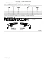
Tableau 1. Protection des yeux pour le coupage au plasma d’arc

Intensité de courant en ampères

Filtre de teinte (minimum)

Moins de 20

no. 4

20 


 40

no. 5

40 


 60

no. 6

60 


 100

no. 8

Certaines applications de coupage produisent un

bruit constant, ce qui peut endommager l’ouïe si le
niveau  sonore  dépasse  les  limites  permises  par

l’OSHA (reportez


vous aux Principales normes de

sécurité).

LE BRUIT peut endommager l’ouïe.

D

Utilisez des protège


tympans ou un serre


tête antibruit si le ni-

veau sonore est élevé.

D

Prévenez toute personne sur les lieux du danger relié au bruit.

LES  FUMÉES  ET  LES  GAZ  peuvent

être dangereux.

Le coupage produit des vapeurs et des gaz.

Respirer  ces  vapeurs  et  ces  gaz  peut  être
dangereux pour la santé.

D

Ne mettez pas votre tête au


dessus des vapeurs. Ne respirez pas

ces vapeurs.

D

Si vous êtes à l’intérieur au moment du coupage, ventilez la pièce
ou ayez recours à une ventilation aspirante installée près de l’arc
pour évacuer les vapeurs et les gaz.

D

Si la ventilation est médiocre, utilisez un respirateur anti


vapeurs

approuvé.

D

Lire et comprendre les spécifications de sécurité des matériaux
(MSDS) et les instructions du fabricant concernant les métaux, les
consommables, les revêtements, les nettoyants et les dégrais-
seurs.

D

Travaillez dans un espace restreint uniquement s’il est bien ventilé
ou si vous portez un respirateur anti


vapeurs. Les vapeurs cau-

sées par le coupage et l’épuisement de l’oxygène peuvent altérer la
qualité de l’air et entraîner des blessures ou la mort. Assurez


vous

que l’air ambiant est sain pour la santé.

Summary of Contents for AIRFORCE 700I

Page 1: ...AirForce 700i And HP 70 Torch Processes Description Air Plasma Cutting Air Plasma Cutter OM 244 013C 2010 04 File Plasma Cutters ...

Page 2: ...ontinue the tradition They re just as committed to providing equipment and service that meets the high standards of quality and value established in 1929 This Owner s Manual is designed to help you get the most out of your Miller products Please take time to read the Safety precautions They will help you protect yourself against potential hazards on the worksite We ve made installation and operati...

Page 3: ...ting A Location 13 4 6 Connecting Gas Air Supply 13 4 7 Connecting Work Clamp 13 4 8 Electrical Service Guide 14 4 9 Extension Cord Data 14 4 10 Serial Number And Rating Label Location 15 4 11 Connecting 1 Phase Input Power For 240 VAC 15 4 12 Wiring Optional 240 Volt Plug 119 172 For Connection To Bobcat Trailblazer Or Champion 10 000 16 4 13 Installing Alternative Plug 17 4 14 Cable Management S...

Page 4: ......

Page 5: ...s high shoes and a cap D Do not locate unit on or over combustible surfaces D Remove any combustibles such as a butane lighter or matches from your person before doing any cutting D After completion of work inspect area to ensure it is free of sparks glowing embers and flames D Use only correct fuses or circuit breakers Do not oversize or by pass them D Follow requirements in OSHA 1910 252 a 2 iv ...

Page 6: ...Ss and the manufacturer s instruction for metals to be cut coatings and cleaners D Work in a confined space only if it is well ventilated or while wearing an air supplied respirator Fumes from cutting and oxygen depletion can alter air quality causing injury or death Be sure the breathing air is safe D Do not cut in locations near degreasing cleaning or spraying oper ations The heat and rays of th...

Page 7: ...ear gas cylinders or any other accessories D Use equipment of adequate capacity to lift unit D If using lift forks to move unit be sure forks are long enough to ex tend beyond opposite side of unit D Keep equipment cables and cords away from moving vehicles when working from an aerial location D Follow the guidelines in the Applications Manual for the Revised NIOSH Lifting Equation Publication No ...

Page 8: ...cational Eye And Face Protec tion ANSI Standard Z87 1 from American National Standards Institute 25 West 43rd Street New York NY 10036 phone 212 642 4900 web site www ansi org Standard for Fire Prevention During Welding Cutting and Other Hot Work NFPA Standard 51B from National Fire Protection Association Quincy MA 02269 phone 1 800 344 3555 website www nfpa org OSHA Occupational Safety and Health...

Page 9: ...e coupez pas sur un contenant fermé tel qu un réservoir ou un bi don D Fixez le câble de masse sur la pièce à couper le plus près possible de la zone à couper afin de prévenir que le courant de coupage ne prenne une trajectoire inconnue ou longue et ne cause ainsi une décharge électrique d étincelles ou un feu D Ne pas utiliser le coupeur plasma pour dégeler des conduites ge lées D Ne coupez jamai...

Page 10: ...adéquats afin de protéger vo tre peau D Ayez recours à des protège tympans ou à un serre tête ignifuges afin d éviter que les étincelles n entrent dans vos oreilles Les rayons d arc provenant du procédé de coupage produisent des rayons visibles et invisibles intenses ultraviolets et infrarouges qui peuvent entraîner des brûlures aux yeux et à la peau LES RAYONS D ARC peuvent entraî ner des brûlure...

Page 11: ...ne basculent D Les bouteilles ne doivent pas être près de la zone de coupage ni de tout autre circuit électrique D Un contact électrique ne doit jamais se produire entre un chalu meau de plasma d arc et une bouteille D Ne coupez jamais sur une bouteille pressurisée une explosion en résulterait D Utilisez uniquement des bouteilles de gaz des détendeurs des boyaux et des raccords conçus pour l appli...

Page 12: ...les D Ne pas surcharger l installation électrique s assurer que l alimen tation est correctement dimensionné et protégé avant de mettre l appareilen service LES CHARGES ÉLECTROSTATI QUES peuvent endommager les cir cuits imprimés D Etablir la connexion avec la barrette de terre avant de manipuler des cartes ou des pièces D Utiliser des pochettes et des boîtes antistatiques pour stocker déplacer ou ...

Page 13: ...phone 800 463 6727 site internet www csa international org Safe Practice For Occupational And Educational Eye And Face Protec tion ANSI Standard Z87 1 de American National Standards Institute 25 West 43rd Street New York NY 10036 téléphone 212 642 4900 site Internet www ansi org Standard for Fire Prevention During Welding Cutting and Other Hot Work NFPA Standard 51B de National Fire Protection Ass...

Page 14: ...h Ground Single Phase Constant Current Voltage Input On Off Percent Direct Current U0 Rated No Load Voltage Average U1 Primary Voltage U2 Conventional Load Voltage Line Connection I1max Rated Maximum Supply Current I2 Rated Welding Current X Duty Cycle Single Phase Static Frequency Converter Transformer Rectifier IP Degree Of Protection Loose Shield Cup Input Hz Hertz I1eff Maximum Effective Suppl...

Page 15: ... Volts DC 230 Volts Duty Cycle at 1045 F 405 C at rated conditions U1 I1 U2 I2 based on a 10 minute period Duty Cycle Amps DC I2 Volts AC RMS U1 50 40 A 208 Volts 50 40 A 230 Volts General Operating Temperature 5 to 104 F 15 to 40 C IP Code Degree of protection provided by enclosure IP23CS IP International Protection 2 No ingress of foreign objects 12 5 mm 0 5 in 3 No harmful ingress spraying wate...

Page 16: ...duty cycle before cutting or gouging NOTICE Exceeding duty cycle can damage unit and void warranty Overheating sduty1 5 95 Ref 244 405 A For Units Connected to a 208 Volt Circuit or a 230 Volt Circuit 50 Duty Cycle At 40 amperes 140 volts DC 0 15 Minutes A OR Reduce Duty Cycle 5 Minutes Cutting 5 Minutes Resting 50 dutycycle 14 1 4 in 362 mm 4 3 Power Source Dimensions And Weight loc_2 3 96 Ref 24...

Page 17: ...nly clean dry air with 90 to 120 psi 621 to 827 kPa pressure 1 Gas Air Inlet Opening 2 Hose 3 Teflon Tape Obtain hose with 1 4 NPT right hand thread fitting Wrap threads with teflon tape optional or apply pipe sealant and install fitting in opening Route hose to gas air supply Tools Needed 3 From Gas Air Supply 1 2 9 16 in 4 7 Connecting Work Clamp Do not connect work clamp to the portion of the w...

Page 18: ...AWG 4 10 10 Reference 2008 National Electrical Code NEC including article 630 1 If a circuit breaker is used in place of a fuse choose a circuit breaker with time current curves comparable to the recommended fuse 2 Time Delay fuses are UL class RK5 See UL 248 3 Normal Operating general purpose no intentional delay fuses are UL class K5 up to and including 60 amps and UL class H 65 amps and above 4...

Page 19: ...t green or green yellow conductor to supply grounding terminal first and never to a line terminal 1 Black And White Input Conductor L1 And L2 2 Green Or Green Yellow Grounding Conductor 3 Input Power Cord 4 Disconnect Device switch shown in the OFF position 5 Disconnect Device Grounding Terminal 6 Disconnect Device Line Terminals Connect green or green yellow grounding conductor to disconnect devi...

Page 20: ...nal And Prong 5 Load 2 Brass Terminal And Prong 6 Ground Brass Terminal And Prong 7 Black And White Input Conductors 8 Green Or Green Yellow Ground Conductor Always connect green or green yellow wire to ground terminal never to a load terminal Connect black L1 and white L2 wires to load terminals Tools Needed 7 Green Or Green Yellow 2 3 4 5 6 240V 8 3 16 in 8 7 6 5 4 3 Plug Front View Engine Contr...

Page 21: ...separate conductors Strip conductors enough to make good contact with plug terminals Make plug connections and reinstall outer shell and cord grip Tighten assembly screws onto shell Do not overtighten Ref 801 305 A 801 611 This procedure is necessary if the unit is to be connected to a 208 230 VAC receptacle that requires a plug that is different from the supplied plug Tools Needed 1 6 7 2 3 4 5 4...

Page 22: ...s List is available at www MillerWelds com OM 244 013 Page 18 4 15 Electrode Wrench 244 412 A Ref 804 885 A 1 Cable Management Strap 2 Electrode Wrench The electrode wrench is fastened to the cable management strap 2 1 ...

Page 23: ...120 VAC input power and the overload protection on the input power circuit fre quently opens either reduce the cutting out put and or the cut time or find more adequate power see Section 4 1 2 Power Light 3 Trouble Lights See Section 6 4 243 013 A 3 1 2 20 25 35 30 CUTS 40 1 2 CLEAN CUT STEEL 7 8 SEVER CUT STEEL 3 8 STAINLESS 3 8 ALUMINUM 3 8 GALVANIZED 1 4 BRASS V POWER TEMP ON OFF V PRESSURE CUP...

Page 24: ... 1321 3 8 9 5 28 711 1 2 12 7 14 345 5 8 15 9 9 224 3 4 19 1 6 163 Travel speeds are approximately 80 if maximum The best cut quality is achieved by cutting near the table value Cutting below the value too slow will result in excess dross Cutting above the value too fast will cause blowback and lack of penetration 5 3 Trigger Safety Lock 1 Trigger Ref 804 848 A 1 Trigger Locked When Button Is In F...

Page 25: ...n paint free location on workpiece as close to cutting area as possible 90 DO NOT start pilot arc without cutting as this shortens the life of the tip and electrode Sparks should pass through the workpiece and out the bottom when cutting If sparks flare back from surface this usually is an indication that travel speed is too fast DO NOT put pressure on shield when drag cutting instead slide shield...

Page 26: ...peed and tip life Slide trigger lock back Press trigger Pilot arc starts After cutting arc starts slowly move torch across metal Adjust speed so sparks go thru metal and out bottom of cut Pause briefly at end of cut before releasing trigger Torch air cooling postflow continues after releasing trigger Postflow must finish before trigger will restart pilot arc The pilot arc starts immediately when t...

Page 27: ...kpiece Slide trigger lock back Press trigger Pilot arc starts After cutting arc starts slowly move torch across metal Adjust speed so sparks go thru metal and out bottom of cut Pause briefly at end of cut before releasing trigger Torch air cooling postflow continues after releasing trigger Postflow must finish before trigger will restart pilot arc 1 16 in 1 6 mm The pilot arc starts immediately wh...

Page 28: ...ea as possible Hold torch at an angle to the workpiece Slide trigger lock back Press trigger Pilot arc starts Move torch to upright position 90 to surface Start cutting when arc pierces workpiece Maintain torch position and continue cutting Release trigger Postflow cooling continues after releasing trigger Postflow must finish before trigger will restart pilot arc The pilot arc starts immediately ...

Page 29: ...severe conditions n Check Z Change Clean l Replace To be done by Factory Authorized Service Agent Reference Each Use Section 4 1 6 5 n Gas Air Pressure n Torch Tip Electrode And Shield Cup Every Week Section 6 4 n Shield Cup Shutdown System Every 3 Months Section 6 2 8 l Damaged Or Unreadable Labels Air Filter Regulator l Cracked Parts n l Gas Air Hose n l Torch Body Cable Every 6 Months OR Inside...

Page 30: ... removing wrapper from unit Turn power Off and disconnect input power plug from receptacle Remove wrapper from unit 1 Filter Base 2 Filter 3 Filter Cup Unscrew filter cup from base Remove cup Unscrew filter element from base Check filter element for dirt and moisture and replace if necessary Be sure that all parts are clean and dry Reinstall filter element and secure filter cup Reinstall wrapper 2...

Page 31: ... pressed again whichever comes first No arc was established Check consumables or torch Cup Repetitive flashing rate of two quick cycles then a one second pause for a 15 second period or until torch trigger is pressed again whichever comes first No pilot arc established possibly due to a loss of current Check consumables Cup Repetitive flashing rate of three quick cycles then a one second pause for...

Page 32: ... parts in reverse order 7 Stand off Guide Placing the stand off guide on the end of the torch provides an optional method of maintaining a 1 16 in 1 6 mm gap between tip and workpiece Make sure this area is clean of any debris Make sure swirl ring is clean of any debris and no holes are obstructed New Worn 1 32 in 1 mm 1 16 in 2 mm maximum pit depth depending on acceptable cut quality 4 3 6 1 Repl...

Page 33: ...nected to circuit board PC1 Route torch white and red leads and work black lead through sleeving the same way as the unit was originally 6 Ring Terminal And TORCH WHITE Terminal Connect ring terminal on end of torch white lead to TORCH WHITE terminal 7 Ring Terminal And TORCH RED Terminal Connect ring terminal on end of torch red lead to TORCH RED terminal Tighten strain relief screw Work Cable Co...

Page 34: ...heck gas air system for leaks Check filter element see Section 6 2 Pressure status light On Check for sufficient gas air supply pressure see Section 4 1 Check for dirty air filter and replace if necessary see manufacturer s instructions Check air lines for leaks Have Factory Authorized Service Agent check pressure switch and control board Cup status light On Check torch shield cup see Section 6 4 ...

Page 35: ...8 in 3 2 mm workpiece see Section 5 6 Clean or replace torch consumables as necessary see Section 6 5 Sparks come out top of cut or cut is not clean Torch travel speed too fast reduce travel speed see Section 5 2 Clean or replace torch consumables as necessary see Section 6 5 Be sure work clamp is securely attached to workpiece Unit not capable of cutting metals thicker than rating see Section 5 2...

Page 36: ...OM 244 013 Page 32 SECTION 7 ELECTRICAL DIAGRAM Figure 7 1 Circuit Diagram ...

Page 37: ...OM 244 013 Page 33 244 011 B ...

Page 38: ...cription Part No Dia Mkgs Item No Recommended Spare Parts Quantity 244 122 TORCH HP 70 16 4ft 5 m hand held replacement 1 208 820 CLAMP work 1 770 654 CONSUMABLE KIT tip electrode 2 770 655 CONSUMABLE KIT cup swirl ring O ring 1 227 877 FILTER air element 1 232 257 CABLE work 1 233 321 STAND OFF GUIDE HP 25 50 70 PLASMA TORCH 1 233 046 WRENCH electrode 1 245 993 KIT detect leads 1 A complete Parts...

Page 39: ...ables No Labor 5 6 Months Parts Batteries Bernard Guns No Labor Tregaskiss Guns No Labor 6 90 Days Parts Accessory Kits Canvas Covers Induction Heating Coils and Blankets Cables and Non Electronic Controls M Guns MIG Guns and Subarc SAW Guns Remote Controls and RFCS RJ45 Replacement Parts No labor Roughneck Guns Spoolmate Spoolguns Miller s True Blue Limited Warranty shall not apply to 1 Consumabl...

Page 40: ...h your personal records Always provide Model Name and Serial Style Number Contact a DISTRIBUTOR or SERVICE AGENCY near you Welding Supplies and Consumables Options and Accessories Personal Safety Equipment Service and Repair Replacement Parts Training Schools Videos Books Technical Manuals Servicing Information and Parts Circuit Diagrams Welding Process Handbooks Contact the Delivering Carrier to ...

Reviews: