


Section 3. Adjustment/Test
1. General
These adjustment and test procedures are applicable to testing and adjusting the generator set after
major repair, major parts replacement, or overhaul.
2. Generator Set Test
a. Pre-operation Test Procedures
(1)
Connect cables from the generator output terminals to a load bank. Use cables of the same
size and length as those to be used in service. Be sure the generator output “N” cable is
grounded.
(2)
Check engine oil level. Oil should be at FULL mark on gage rod.
(3)
Check tension of fan and generator V-belts.
(See Section 2-1, Figure 5 and 6)
.
(4)
If governor throttle linkage was changed, check all linkage to make certain engine speed may be
controlled when started. See Figure 15.
(5)
Inspect for oil and fuel leaks.
(6)
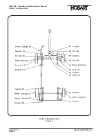
If the setting of the voltage regulator rheostat
(37, Fig. 1)
has been changed, set at CENTER
position
(halfway between full clockwise position and full counterclockwise position.)
(7)
Check engine circuit fuse
(41, Fig. 1)
by placing panel light switch
(31)
in ON position. If panel
lights (2) operate, the fuse (41) switch (31) and lamps are good.
(8)
Check fault indicating lights
(10)
by pressing test switch
(8)
. If lights glow, fuse
(41)
and
indicating lamps are good.
(9)
Make a general inspection of all wiring, and terminals. Inspect the equipment to be certain no
damage will result from starting the engine.
(10)
At initial start-up after generator overhaul or repair, “flash” the exciter field momentarily with 12-V
DC to the field windings as follows:
Engine must not be running when field flashing to prevent voltage regulator
damage.
a. Flashing exciter field using test box.
•
If a test box
(see Sect. 1-3, Fig. 3)
is available, connect it to receptacle connector (Sect.
1-3, Fig. 4).
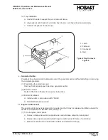
(aa) Rotate the selector knob
(Sect. 1-3, Fig. 3, Item 1)
to position 8.
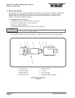
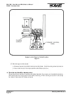
(bb) Use two jumper leads, each equipped with an alligator clip and a test prod, to connect
12 V DC power to test jacks
(2 and 3)
on the box. Connect positive jumper from input
terminal on starter solenoid
(2, Fig. 2)
to red test jack. Connect negative lead from starter
ground terminal
(3, Fig. 2)
to black test jack.
(cc) Momentarily pressing pushbutton switch
(Sect. 1-3, Fig. 3, item 2)
will flash the exciter
field.
(dd) Disconnect jumper leads.
CAUTION
OM-2040 / Operation and Maintenance Manual
90D20 / Generator Sets
February 28/94 Revised
Chapter 2-3
Page 1
Summary of Contents for 6921 Series
Page 2: ...This page intentionally left blank ...
Page 223: ......
Page 224: ......
Page 225: ......
Page 226: ......
Page 227: ......
Page 228: ......
Page 229: ......
Page 230: ......
Page 231: ......
Page 232: ......
Page 233: ......
Page 234: ......
Page 235: ......
Page 236: ......
Page 237: ......
Page 238: ......
Page 239: ......
Page 240: ......
Page 241: ......
Page 242: ......
Page 243: ......
Page 244: ......
Page 245: ......
Page 246: ......
Page 247: ......
Page 248: ......
Page 249: ......
Page 250: ......
Page 251: ......
Page 252: ......
Page 253: ......
Page 254: ......
Page 255: ......
Page 256: ......
Page 257: ......
Page 258: ......
Page 259: ......
Page 260: ......


