background image

85

10.1.2 List of servo parameters

The parameter list is as follows.

(Note) The following parameters are factory settings and should not be changed.

• Appointment Parameters

• Parameters not recorded in this manual

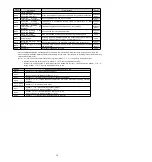
Pn No.

Size

Name

Setting range

Setting

Unit

Factory setting Available

time

Categor

y

Rema

rks

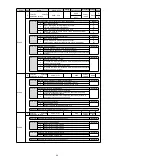
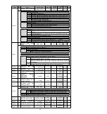
Pn000

2 Function selection Basic

switch 0

0000

10B1

-

0000

Power

restart

Setup

-

n.



X

Rotation direction selection

Remarks

0

The CCW direction is the forward rotation direction.

1

The CW direction is the forward rotation direction. (Reverse mode)

n.



X

Control mode selection

Model

0

Speed control (analog command)

P

1

Position control (pulse sequence command)

2

Rotational moment control (analog command)

3

Internal set speed control (contact command)

4

Internal set speed control (contact command)

speed control (analog

command

5

Internal set speed control (contact command)

position control

(pulse sequence command)

6

Internal set speed control (contact command)

torque control

(analog command

7

Position control (pulse sequence command)

speed control (analog

command)

8

Position control (pulse sequence command)

torque control (analog

command)

9

Torque control (analog command)

speed control (analog command)

A

Speed control (analog command)

speed control with zero position

fixing function

B

Position control (pulse sequence command)

position control with

command pulse disable function

n.

X



Appointment parameters (do not change it)

n.X



Startup selection when encoder is not connected

Remarks

0

It is started as the corresponding servo drive of the rotary servo motor

when the encoder is not connected.

1

It is started as the corresponding servo drive of the linear servo motor

when the encoder is not connected.

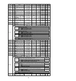
Pn001

2 Function

selection

application switch 1

0000

1142

-

0000

Power

restart

Setup

-

n.



X

Servo OFF and Stop Method in Gr.1 Alarm

Remarks

0

Stop the motor by DB (dynamic brake).

1

Stop the motor through DB, and then cancel DB.

2

Do not use DB, set the motor to run freely.

n.



X

Stop Method when it is overtravel (OT)

Remarks

0

DB stop or free running stop (stop method is the same as Pn001=

n.



X).

1

The set torque of Pn406 is used as the maximum torque to decelerate

and stop the motor, and then the servo lock state is entered.

2

The set torque of Pn406 is taken as the maximum torque to decelerate

and stop the motor, and then enter the free running state.

3

According to the deceleration time of Pn30A, the motor decelerates

and stops, and then enters the servo locking state.

4

According to the deceleration time of Pn30A, the motor will decelerate

and stop, and then enter the free running state.

n.

X



Selection of AC/DC input for main loop power supply

Remarks

0

AC power is input from L1, L2, L3 and L3 terminals as the main loop

power (no universal converter is used).

1

Between B1/

,

the input DC power supply is as the main loop

power supply (using an external converter or a universal converter).

n.X



Appointment parameters (do not change it)

Summary of Contents for HSD7-B Series

Page 1: ...HSD7 E Series AC Servo Drive User s Manual HNC Electric Limited ...

Page 2: ...motor Servo OFF Not supplying power to the motor Servo lock A state in which the motor is stopped and is in a position loop with a position reference of 0 Main loop cable Cables connected to main circuit terminals main circuit power cable control power cable servo motor main circuit cable etc Labeling of icons The following icons are designed in this book to make readers understand the distinction...

Page 3: ...The contents are all important contents related to safety Please observe them Danger Indicates an emergency situation that is likely to result in death serious injury and fire if not avoided Warning Indicates a dangerous situation that may lead to death serious injury and fire if not avoided Notes Indicates a dangerous situation that may lead to moderate minor injuries and fire if not avoided Noti...

Page 4: ...nd Brake 18 4 5 Connection of input and output signals 19 4 5 1 Name and function of input output signal connector CN1 19 4 5 2 Pin Arrangement of Input and Output Signal Connector CN1 19 4 5 3 Examples of wiring for input and output signals 20 4 5 4 Input output loop 22 Chapter 5 Basic functions to be set before operation 24 5 1 Operation of Parameters Pn 24 5 1 1 Classification of the parameter ...

Page 5: ...nals 40 6 1 3 Servo Alarm Output ALM Signal 40 6 1 4 Warning output WARN signal 40 6 1 5 Rotation detection output TGON signal 40 6 1 6 Ready output S RDY signal 41 6 1 7 Speed consistent output V CMP signal 41 6 1 8 Positioning Completion COIN Signal 42 6 1 9 Position nearby output NEAR signal 42 6 1 10 Speed limit function during torque control 43 6 2 Operation for Momentary Power Interruptions ...

Page 6: ...Signal FA00E 65 8 4 12 Write inhibit setting of parameters FA010 65 8 4 13 Displays the motor model FA011 65 8 4 14 Display software version FA012 66 8 4 15 Single parameter adjustment FA203 66 8 4 16 EasyFFT Fn206 67 8 4 17 Load Inertia Mass Detection FA208 68 Chapter 9 Maintenance 69 9 1 Inspection and component replacement 69 9 1 1 Inspection 69 9 1 2 Battery Replacement 69 9 2 Alarm display 70...

Page 7: ...ccuracy The servo drive can maximize the performance of the machine in the shortest possible time and help to improve production efficiency HSD7 series servo drivers include single axis HSD7 ES BS series servo drivers and double axis HSD7 EW BW series servo drivers 1 2 Distinguishing Method of Nameplate The basic information marked on the drive nameplate is shown in the following figure ...

Page 8: ...unications 25 25 A 20 MECHATROLINK Ⅲ Communications 30 EtherCAT Communications The maximum specification of continuous output current for biaxial drive is 10 Three phase 380VAC HSD7 ES _ 15 D 00 HSD7 Series Axis Number Continuous Output Current Power Supply Voltage Interface Type Axis Number Contionous Output Current Power Supply Voltage Interface Type S Single 15 15 A D 380VAC 00 Analog standard ...

Page 9: ...9 Regenerative Resistor Built In Regenerative Resistor Resistance Ω 40 20 20 20 12 20 Capacity W 80 80 80 80 150 120 Minimum Allowable External Resistance Ω 40 20 15 15 15 15 10 Overvoltage Category III Three phase 380VAC Model No 15D 18D 24D 35D Continuous output current Arms 15 18 24 35 Maximum instantaneous output current Arms 35 3 44 1 58 9 88 3 Main power supply Input power requirements AC30V...

Page 10: ...imum can be N 127 stops Axis address setting Through parameter setting MECHATROLINK Ⅱ Bus Communication protocol MECHATROLINK II Set slave address 41 to 5F hexadecimal maximum number of slave stations supported 30 via parameter setting Baud rate 10 Mbps 4 Mbps via parameter setting Transmission period 250 microseconds or 0 5 milliseconds to 4 0 milliseconds multiples of 0 5 milliseconds Number of ...

Page 11: ...160 5 150 0 5 mounting pitch 安装间距 35 5 5 HSD7 06A 70 160 180 Mounting Hole Diagram 安装孔图 单位 毫米 Unit mm 64 160 6 148 0 5 mounting pitch 安装间距 6 3 M4 6 58 0 5 安装间距 mounting pitch HSD7 10A Mounting Hole Diagram 安装孔图 单位 毫米 Unit mm 160 90 180 84 160 6 148 0 5 mounting pitch 安装间距 6 78 0 5 安装间距 mounting pitch 6 3 M4 ...

Page 12: ... 安装间距 mounting pitch 6 HSD7 16A HSD7DS 25A HSD7 15D HSD7 18D 110 单位 毫米 Unit mm 220 200 Mounting Hole Diagram 安装孔图 98 0 5 6 6 220 6 209 0 5 mounting pitch 安装间距 安装间距 mounting pitch HSD7 24D HSD7 35D 350 236 194 Mounting Hole Diagram 安装孔图 单位 毫米 Unit mm 33 170 33 350 9 335 0 5 mounting pitch 安装间距 4 M6 安装间距 mounting pitch ...

Page 13: ...e vertical direction as shown in the right figure In addition please make the front surface panel display part of servo drive face the operator for installation Note Please firmly fix the servo drive on the mounting surface through 2 4 mounting holes the number of mounting holes varies according to the capacity 3 3 Mounting hole dimensions Please use the mounting hole to firmly fix the servo drive...

Page 14: ...ile the CHARGE lamp is on Otherwise it will lead to electric shock Please follow the precautions and procedures recorded in this manual for wiring and trial operation Servo drive failure caused by wrong wiring of brake circuit and application of abnormal voltage may lead to mechanical damage or casualties Please wire correctly and reliably The connector and the pin arrangement of the connector var...

Page 15: ...F the power supply Frequent ON OFF power supply will lead to aging of internal components of servo drive so do not frequently ON OFF power supply except for necessary applications The power ON OFF interval should be more than 1 hour roughly standard after starting the actual operation normal operation Please observe the following precautions when wiring to use the servo system safely and stably Pl...

Page 16: ...tions Please observe the following precautions when wiring and connecting interference filters Please separate the input wiring from the output wiring In addition do not put the input and output wires into the same sleeve nor bind them together Servo motor Above 2 0mm2 Interference filter Above 2 0mm2 Above 2 0mm2 Servo unit Interference filter 2 CD power supply Grounding plate Operation relay seq...

Page 17: ...Please connect the ground wire of this filter and the ground wire of other equipment in the control cabinet to the ground plate of the control cabinet when there is an interference filter inside the control cabinet and then connect to the ground Can be close to the input line Interference filter Interference filter Grounding plate Grounding plate Grounding plate Grounding plate Interference filter...

Page 18: ... from the servo drive main loop through the floating capacitor of the servo motor when the servo motor is mechanically grounded Please be sure to connect the motor housing terminal FG or ground terminal FG of the servo motor with the ground terminal of the servo drive in order to prevent this phenomenon In addition the ground terminal must be grounded When noise occurs in cables for input and outp...

Page 19: ...erminal for AC power supply input Three phase AC 200V 240V 15 10 50 60Hz Single phase AC 200V 240V 15 10 50 60Hz L1C L2C Control power terminal Single phase AC 200V 240V 15 10 50 60Hz B1 B2 B3 Regenerative resistor connection terminal Remove the short wire or short piece between B2 B3 when the regeneration capacity is insufficient and connect the external regeneration resistor between B1 and B2 Pl...

Page 20: ...g edge width of 3 0mm 3 5mm 1 Remove the main circuit connector and motor connector from the servo drive 2 Peel off the cladding of the used wires 3 Use a tool to open the wire insertion part of the terminal connector There are two methods of opening You can choose any of them Use method of spring opener Use method of flat screwdriver The opening operation is performed using a spring opener as ill...

Page 21: ...f the regenerative resistor In particular do not short circuit B1 B2 Otherwise the regenerative resistor and servo drive will be damaged and fire will occur Connection method of regenerative resistor 1 Remove the wire between terminals B2 B3 of servo drive 2 Connect external regenerative resistor to B1 and B2 terminals 3 Set Pn600 regenerative resistance capacity and Pn603 regenerative resistance ...

Page 22: ...r 4 E Battery for absolute value encoder 5 SD Encoder serial data 6 SD Encoder serial data Housing Shielded Incremental encoders do not require wiring 4 4 3 Connection of Servo Drive and Encoder Absolute value encoder When using absolute value encoder please install battery on encoder cable with battery unit Example of Wiring Using Encoder Cable with Battery Unit Battery 3 6V Absolute position Con...

Page 23: ...te in case of emergency stop The brake control output BK signal can change the distribution of the output signal When using the 24V brake the DC 24V power supply must be separated from the input and output signals CN1 and other power supplies separately Common power supply will lead to misoperation of input and output signals Servo unit Example of relay circuit Photocoupler Emergency stop Servo un...

Page 24: ...butable Ex factory P CON Input outlet 1 redistributable Ex factory A axis P CON 40 IN5 Input outlet 5 redistributable Factory Reservation Input outlet 5 redistributable Ex factory b axis P CON 16 IN2 Input outlet 2 redistributable Ex factory P OT Input outlet 2 redistributable Ex factory A axis P OT 41 IN6 Input outlet 6 redistributable Factory Reservation Input outlet 6 redistributable Ex factory...

Page 25: ...wer supply is DC 24V When using the built in regenerative resistor terminals B2 and B3 need to be shorted When using external regenerative resistor B2 and B3 terminals need to be disconnected Model 24 35D has no built in regenerative resistor Reserved Reserved Reserved Reserved Reserved Reserved Reserved ...

Page 26: ... using the built in regenerative resistor terminals B2 and B3 need to be shorted When using external regenerative resistor B2 and B3 terminals need to be disconnected Model 24 35D has no built in regenerative resistor Reserved Reserved Reserved Reserved Reserved Reserved Reserved ...

Page 27: ...p Common emitter loop Polarity of input signal Polarity of input signal Photocoupler Internal level signal Photocoupler Internal level signal ON L level ON L level OFF H level OFF H level Sequential control output loop Important The output circuit may be short circuited due to wrong wiring and application of abnormal voltage The brake does not operate which may lead to mechanical damage or casualt...

Page 28: ...er are as follows Maximum allowable voltage DC30 V Current range DC5 50 mA Output loop of linear driver Next the CN1 19 24 A B C phase signals terminals of CN1 port will be described The serial data of the encoder is converted into output signals PAO PAO PBO PBO of 2 phase A phase B phase pulses and origin signals PCO PCO in one coil of the encoder are output through the output loop of the linear ...

Page 29: ... and function selection type for selecting function Speed Indicates the control mode in which this parameter can be used Numerical setting type Function selection type speed control position control Position Torque torque control Velocity loop gain Setting range Setting Unit Factory setting Effective time Effective immediately Speed Position Category Adjustment Parameter number Represents a config...

Page 30: ...parameter must not be set to write inhibit Must be in servo OFF state 5 2 Setting of Communication Specifications for MECHATROLINK II The communication specification of MECHATROLINK II is set by servo drive parameters PA013 and PA014 5 2 1 Communication specification setting Parameter Meaning Effective time Category Pn014 n 0 Communication speed setting 0 4Mbps 1 10Mbps Power restart Setup n 1 Fac...

Page 31: ...nform to the actual power input specification A 330 main circuit power supply wiring error will occur Example of A 330 Main Circuit Power Supply Wiring Error When it is set to input AC power for use Pn 001 n 0 DC power is input between B1 terminals When the input DC power source is set to be used Pn 001 n 1 AC sources are input to L1 L2 and L3 terminals Parameter Meaning Effective time Category Pn...

Page 32: ...or stopped by turning on or off the S ON signal and AC power supply internal components may be aged resulting in motor failure 2 Please input S ON signal when the servo motor is stopped The servo cannot be turned ON when the motor rotates 5 6 2 Set to Constant Servo ON Motor Energized Pn50A n X servo ON input S ON signal distribution is set to 9 when S ON signal is set to constant servo on motor o...

Page 33: ...n function Notes In order to prevent accidents caused by poor contact and disconnection of contact parts please use normally closed contact for limit switches In addition do not change the factory setting of the polarity of over travel signals P OT N OT When the servo motor is used as a vertical shaft the brake control output BK signal will remain in the ON brake on state in the overtravel state s...

Page 34: ...ree running operation n 1 Decelerate according to Pn406 setting Zero position fixing n 2 Free running operation n 3 Decelerate according to Pn30A setting Zero position fixing n 4 Free running operation Torque control cannot slow down to stop According to the setting of Pn001 n X servo OFF and stop method in case of Gr 1 alarm the dynamic brake stops or the free running stops and enters the free ru...

Page 35: ...arnings is as follows 1 Warnings will be detected for overtravels in the same direction as the command 2 Warning cannot be detected for overtravel in the direction opposite to the command direction For example even if the N OT signal is ON a warning will not be issued during the movement under the command of the positive direction 3 In the absence of commands warnings will be detected for overtrav...

Page 36: ...nnector pin number of the allocation target can be changed Please refer to Distribution of Brake Control Output BK Signal for details When the servo is OFF or an alarm is detected the BK signal is OFF brake action The time when the brake is operated the time when the BK signal is turned OFF is adjusted by the servo OFF delay time Pn506 Type Signal name Connector pin number Signal status Meaning Ou...

Page 37: ... Important When multiple signals are distributed to the same output terminal OR logic is used for signal output Please avoid duplication with other signals when distributing BK signals In particular please avoid distributing the rotation detection output TGON signal and BK signal to the same output terminal If it is distributed to the same terminal the TGON signal will be turned ON at the speed of...

Page 38: ...gnal can be adjusted by setting the brake command output speed value Pn507 and the servo OFF brake command waiting time Pn508 Note When the stop method for alarm occurs is zero speed stop the setting of Pn506 brake command servo OFF delay time shall be followed after the motor stops Pn507 Brake command output speed value Speed Position Torque Setting range Setting Unit Factory setting Effective ti...

Page 39: ...e use the servo drive applicable to the dynamic brake option Regarding the stopping method during alarm in order to try to shorten the inertial moving distance when the alarm occurs the factory settings are all zero speed stop for alarms that allow the selection of zero speed stop However depending on the application sometimes DB stop is more suitable than zero speed stop 5 10 1 Motor Stop Method ...

Page 40: ... of Pn00A n X will be ignored during torque control and the setting of Pn001 n X will be followed 5 11 Motor overload detection value Motor overload detection value refers to the value threshold of detecting overload warning and overload alarm when continuous load exceeding the rated value of servo motor is applied Which can prevent the servo motor from overheating Servo drive can change the detec...

Page 41: ...to the pulse number required for actual movement According to the electronic gear function the workpiece movement amount per pulse of the input command for servo drive is 1 command unit That is if servo driven electronic gears are used the pulses can be converted into command units for reading Note When the upper device sets the electronic gear the servo driven electronic gear ratio is usually 1 1...

Page 42: ...10 encoder backup alarm occurs When A 820 encoder and number check alarm occurs When it is necessary to initialize the rotation number data of the absolute encoder Notes After setting the absolute value encoder the rotation number data is the value of 2 2 coils The reference position of the mechanical system will change so please locate the reference position of the upper device after setting If t...

Page 43: ...ting Unit Factory setting Effective time Category 0 Maximum applicable motor capacity for servo drive 10W 0 Effective immediately Setup Pn603 Regenerative resistor value Speed Position Torque Setting range Setting Unit Factory setting Effective time Category 0 65535 10mΩ 0 Effective immediately Setup The regenerative resistance capacity shall be set to a value matching the allowable capacity of th...

Page 44: ...al Torque Limit Pn50B n X DEC Origin Return Deceleration Switch Input Pn511 n X EXT1 External Latch Input 1 Pn511 n X EXT2 External Latch Input 2 Pn511 n X EXT3 External Latch Input 3 Pn511 n X FSTP Forcibly stop input Pn516 n X Relationship between parameter setting value and assigned pin number and polarity The relationship between the parameter setting value of the input signal and the pin numb...

Page 45: ...utput when the servo drive detects a fault Important Please design an external circuit that turns OFF the power supply of the servo driven main circuit through the alarm output when a fault occurs Type Signal name Connector pin number Signal status Meaning Output ALM Distribution required ON closed Servo drive normal state OFF OFF Servo drive alarm status 6 1 4 Warning output WARN signal The servo...

Page 46: ...required ON closed State in which servo ON SV_ON command can be received OFF OFF The state in which the servo ON SV_ON command cannot be received Note S RDY signal can be distributed It can be set to Pn50E n X distribution of servo ready output S RDY signal and distributed to terminals 6 1 7 Speed consistent output V CMP signal The speed coincidence output V CMP signal is a signal output when the ...

Page 47: ...condition can be added to the output condition of the COIN signal to change the output time When used in a state where the positioning completion amplitude is small and the position deviation is generally small it can be set to Pn207 n X positioning completion output COIN signal output time to change the output time of the COIN signal Parameter Name Content Effective time Category Pn207 n 0 Factor...

Page 48: ...his function Note According to the load condition of the motor there will be a certain gap between the limited speed of the motor and the set value Speed limit detection output VLT signal The output signal of the motor speed after being limited is as follows Type Signal name Connector pin number Signal status Meaning Output VLT Distribution required ON closed Motor speed limitated OFF OFF Motor sp...

Page 49: ...tantaneous power failure time is greater than the set value of Pn509 the servo ready output S RDY signal is OFF and the servo is OFF 2 The control power supply and the main circuit power supply can cope with power outages of more than 5000ms when using non power off equipment 3 The holding time of servo drive control power supply is about 100ms The control power supply cannot be controlled during ...

Page 50: ...orque limit is executed by the upper device n 2 The undervoltage warning is detected and torque limitation is performed by Pn424 torque limitation when the main circuit voltage is reduced and Pn425 torque limitation is performed according to the torque limitation release time when the main circuit voltage is reduced executed by servo drive unit Relevant parameters Servo unit Main circuit input pow...

Page 51: ...tor will become longer When the motor is powered off immediately please use the servo OFF SV_OFF 6 4 Setting of Maximum Speed of Motor The maximum speed of the servo motor is set by the following parameters Pn316 Maximum speed of motor Speed Position Torque Setting range Setting Unit Factory setting Effective time Category 0 65535 1 min 1 10000 Power restart Setup By reducing the maximum speed of ...

Page 52: ...he encoder is processed in the servo drive and then is output after frequency division according to the set value of Pn212 Please set the output number of encoder frequency division pulses according to the system specifications of mechanical and upper devices The setting of the frequency division pulse number of the encoder will be limited by the encoder resolution Note 1 The setting range of the ...

Page 53: ...47 PAO signal PBO signal Setting value 16 1 circle ...

Page 54: ...t Factory setting Effective time Category 1073741823 1073741823 1 Command unit 1073741823 Effective immediately Setup Pn806 Reverse side soft limit Speed Position Torque Setting range Setting Unit Factory setting Effective time Category 1073741823 1073741824 1 Command unit 1073741823 Effective immediately Setup 6 6 3 Carry out soft limit check according to commands Set whether soft limit check is ...

Page 55: ...de is limited to ON Limit value the smaller of the set values of Pn402 and Pn404 OFF OFF The external torque on the forward rotation side is limited to OFF Limit value Pn402 Input N CL Distribution required ON closed The external torque ON the reversal side is limited to ON Limit value the smaller of the set values of Pn403 and Pn404 OFF OFF The external torque on the reversal side is limited to O...

Page 56: ...op position after the power supply is turned OFF In a system using an absolute value encoder the current position can be grasped by an upper controller Therefore when the system is powered on there is no need to perform the origin reset operation There are three encoders for servo motors Each encoder can be specified by setting Pn002 n X Parameter Setting When Using Incremental Encoder Parameter M...

Page 57: ...ution of forced stop input FSTP signal 6 9 2 Selection of Stop Method for Forced Stop Function The stop method of the forced stop function is selected through Pn00A n X stop method at forced stop Parameter Meaning Effective time Category Pn00A n 0 DB stop or free operation stop stop method is the same as Pn001 n X Power restart Setup n 1 Factory setting The set torque of Pn406 is used as the maxim...

Page 58: ...the stop of the motor 6 9 3 Methods of Recovery from Compulsory Stop The recovery method when the operation is stopped by the forced stop input FSTP signal is as follows If a servo ON SV_ON command is received when the forced stop input FSTP signal is OFF the forced stop state will remain unchanged even if the FSTP signal is set to ON Enter the servo OFF SV_OFF command and after entering the base ...

Page 59: ...ervo drive is normal The fastening parts of the servo motor are not loose When using servo motor with oil seal the oil seal is not damaged And oil has been applied When using servo motors stored for a long time the maintenance and inspection of servo motors have been completed For the maintenance and inspection essentials of servo motor please refer to the manual for using servo motor Servo motors...

Page 60: ...ctory setting Effective time Category 0 10000 1 min 1 500 Effective immediately Setup Pn305 Soft start acceleration time Speed Setting range Setting Unit Factory setting Effective time Category 0 10000 1 ms 0 Effective immediately Setup Pn306 Soft start deceleration time Speed Setting range Setting Unit Factory setting Effective time Category 0 10000 1 ms 0 Effective immediately Setup 7 3 2 Operab...

Page 61: ...the un number to be displayed when the power is turned on in Pn52F Pn52F Monitoring display when power is turned on Speed Position Torque Setting range Setting Unit Factory setting Effective time Category 0000 0FFF 0FFF Effective immediately Setup When set to 0FFF factory setting the status will be displayed when the power is turned on Key Name Function Function key Toggle basic mode Status displa...

Page 62: ...out if it exceeds the specified value Displays the rotation detection output TGON signal When the rotation speed of the servo motor is higher than the specified value set by Pn502 or Pn581 and the factory setting value is 20min 1 or 20mm s it will be turned on and when it is lower than the specified value it will be turned off Displayed in speed command input during speed control The input speed c...

Page 63: ...es the setting method of numerical setting type taking the setting value of speed loop gain Pn100 from 40 0 to 100 0 as an example Steps Display after operation Operation key Operation 1 Press the F key to select the parameter mode In case of dual axis drive long press F key more than 3 seconds and Axis A and Axis B will be switched alternately 2 Press UP or DOWN to display Pn100 3 Press S key to ...

Page 64: ...turn to the display of Pn000 8 3 The operation of the monitor display Un in the panel operator A function of monitoring displaying the command value set in the servo drive the state of input and output signals and the internal state of the servo drive Displays the number beginning with UA on the panel operator Display Example Motor Speed The following describes the basic operation of monitoring di...

Page 65: ...ch the A axis and the B axis alternately 3 Press the S key to return to the display of step 1 8 3 2 Monitoring of input and output signals Un005 Un006 Use Un005 Un006 to display the assigned signal status in the segment LED of the panel operator Display discrimination method segment led The input signal OFF corresponding to the LED number is displayed the upper segment lights up The input signal O...

Page 66: ...ne parameter tuning FA206 Easy FFT FA208 Load inertia mass detection 8 4 1 Display of alarm records FA000 Please refer to the following contents besides the operation steps Steps Display after operation Operation key Operation 1 Press the F key to select the auxiliary function If the parameter number does not show FA000 press the UP or DOWN key to show FA000 In case of dual axis drive long press F...

Page 67: ...Press the DOWN key and the servo motor will reverse 6 After the origin search of the servo motor is completed it will change to flashing display At this time the servo motor enters the servo lock state at the origin within 1 coil of the encoder 7 Press the S key again to return to the display of FA003 8 4 4 Program JOG run FA004 Please refer to the following contents besides the operation steps St...

Page 68: ...and the display content is shown in the left figure 4 Press F to delete the alarm record donE will flash and return to the display on the left after the deletion is completed 5 Press the S key again to return to the display of FA006 8 4 7 Absolute value encoder Setup initialization FA008 Please refer to the following contents besides the operation steps Steps Display after operation Operation key ...

Page 69: ...Press the F key to select the auxiliary function 2 UP or DOWN key display FA00A 3 Press S key and the display content is shown in the left figure 4 Turn ON the servo from the outside to display the content on the left 5 Press the S key to display the current offset 6 Press the UP or DOWN key to adjust and stop the servo motor This value is the offset 7 donE will flash and then switch to the displa...

Page 70: ...nt is completed the left display will be returned after flashing donE 5 Press the S key again to return to the display of FA00E 8 4 12 Write inhibit setting of parameters FA010 Please refer to the following contents besides the operation steps Steps Display after operation Operation key Operation 1 Press the F key to select the auxiliary function 2 UP or DOWN key display FA010 3 Press S key and th...

Page 71: ...r resolution 11 Press the S key again to return to the display of FA011 8 4 14 Display software version FA012 Please refer to the following contents besides the operation steps Steps Display after operation Operation key Operation 1 Press the F key to select the auxiliary function 2 UP or DOWN key display FA012 3 Press S to display the servo driven software version as shown in the left figure 4 Pr...

Page 72: ...F key to select the auxiliary function 2 UP or DOWN key display FA206 3 Press S key the display content is as shown in the left figure and enter the command amplitude setting mode 4 Press the UP or DOWN key to set the command amplitude Command amplitude setting range 1 800 Note 1 When setting EasyFFT for the first time do not change the setting of command amplitude and start from the initial setti...

Page 73: ...F again to return to step 5 Note 1 When the notch filters of section 1 and section 2 have been set it is not possible to set the notch filter at Pn408 n 1 1 2 When the notch filter frequency detected by this function is not used Pn408 0 0 0 is set 10 Press the S key again to return to the display of FA206 8 4 17 Load Inertia Mass Detection FA208 Please refer to the following contents besides the o...

Page 74: ...ry Pn008 n 0 Factory setting An alarm is displayed when the battery voltage drops A 830 Power restart Setup n 1 An alarm is displayed when the battery voltage drops A 930 When Pn008 n 0 is set After switching on the power supply and outputting a servo alarm ALM signal for up to 5 seconds monitor the battery voltage for 4 seconds Even if the battery voltage drops below the specified value after 4 s...

Page 75: ...display disappears and the servo drive can operate normally 9 2 Alarm display When the servo drive is abnormal the LED of the panel display unit displays the Alarm number The Alarm number that is occurring is shown below and is displayed in the panel display area Example When A 20 alarm occurs it will display 9 2 1 Warning list The Alarm name Alarm content stop method when alarm occurs and whether...

Page 76: ...ts Abnormal Protection PDO watchdog setting error Gr 1 May A 615 DC set exception protection DC setting error Gr 1 May A 616 SM event mode setting exception protection Unsupported SM events are set Gr 1 May A 617 SM2 3 Set Abnormal Protection SM2 3 is set to an incorrect value Gr 1 May A 620 CAN controller hardware error CAN transceiver hardware error Gr 1 May A 621 CANopen heartbeat timed out Mon...

Page 77: ...s or cutting oil etc the components inside the servo drive have failed Confirm the setting environment Replace the servo drive Servo drive failure Connect to the servo drive power supply again When the alarm still occurs it may be a fault Replace the servo drive A 021 Parameter format exception The data of internal parameters of servo drive is abnormal The software version of the write parameter i...

Page 78: ...and confirm whether there is any effect Take anti interference measures such as correctly wiring FG etc In addition the wire size of FG should be the same as that of servo drive main loop Servo drive failure Connect to the servo drive power supply again When an alarm still occurs replace the servo drive A 300 Regenerative faults The regenerative resistance capacity Pn600 is set to a value other th...

Page 79: ...tom adjustments EasyFFT no adjustment Vibration detected in function The motor vibrates greatly when using the adjustment free function Confirm the waveform of motor speed Reduce the load below the allowable moment of inertia ratio or increase the load value set by the adjustment free value to reduce the rigidity value The motor vibrates greatly when custom adjustment and EasyFFT are performed Con...

Page 80: ...r grating pitch Pn282 Confirm the specifications of linear encoder and set the value correctly The magnetic pole sensor is exposed outside the motor stator Confirm magnetic pole sensor Reinstall the motor rotor or stator Incorrect wiring of magnetic pole sensor Confirm the wiring of magnetic pole sensor Correct the wiring of magnetic pole sensor Magnetic pole sensor failure Replace the magnetic po...

Page 81: ...ble length is too long and is disturbed The longest connection distance of encoder cable is 50m The potential of FG changes due to the influence of motor side equipment welding machine etc Confirm the status of encoder cables and connectors Ground the machine to prevent shunting to encoder side FG The encoder is subject to excessive vibration impact Confirm usage Reduce mechanical vibration Instal...

Page 82: ...pply again When an alarm still occurs replace the servo drive A E61 MECHATROLINK Abnormal transmission period Synchronization Interval Abnormal The transmission period of MECHATROLINK has changed Confirm the transmission cycle setting of MECHATROLINK The reason for the transmission cycle variation of the upper device is eliminated Servo drive failure Connect to the servo drive power supply again W...

Page 83: ...rm numbers Alarm number Alarm name Alarm content Reset A 900 Position deviation is too large The accumulated position deviation exceeds the proportion set by Pn520 Pn51E 100 Need A 901 Excessive position deviation when servo ON The accumulated position deviation during servo ON exceeds the proportion set by Pn526 Pn528 100 Need A 910 Overload Warning display immediately before overload A 710 720 a...

Page 84: ...data outside the range fixed Automatic reset A 9A0 Overtravel Overtravel detected in servo ON need When using MECHATROLINK III standard servo profile command it will automatically reset when receiving normal command When using the MECHATROLINK II compatible configuration file command reset the warning according to the alarm and warning clear command ALM_CLR Note 1 If it is not set to output alarm ...

Page 85: ...ation overload A 320 Power supply voltage exceeds specification range Measure the supply voltage Set the power supply voltage within the specification External regenerative resistance value servo drive capacity or regenerative resistance capacity is insufficient or in a continuous regenerative state Reconfirm operating conditions and capacity Change the regenerative resistance value regenerative r...

Page 86: ... The terminals of the input and output signal connector CN1 have wiring errors and omissions Confirm the connection status of the input and output signal connector CN1 terminals Connect the input and output signal connector CN1 terminals correctly Wiring of servo motor main loop cable and encoder cable falls off Confirm the connection status Correct wiring The servo motor is overloaded Try no load...

Page 87: ... the cables for input and output signals meet the specifications The cable specification double stranded shielded wire or double stranded unified shielded wire with core wire of more than 0 12 mm2 and tinned soft copper stranded wire Use cables that meet specifications Because the encoder cable is too long mutual interference occurs Confirm the cable length for encoder Set the length of encoder ca...

Page 88: ...rference between encoder or serial conversion unit and signal line Anti interference measures shall be taken for the connection of encoder or serial conversion unit Encoder is affected by excessive vibration impact Confirm whether mechanical vibration occurs Confirm the installation state of servo motor precision of installation surface fixed state eccentric core Reduce mechanical vibration And th...

Page 89: ...terference Confirm whether there is mutual interference between encoder or serial conversion unit and signal line Anti interference measures shall be taken for the connection of encoder or serial conversion unit Encoder is affected by excessive vibration impact Confirm whether mechanical vibration occurs Confirm the installation state of servo motor precision of installation surface fixed state ec...

Page 90: ...t parameters do not change it n X Startup selection when encoder is not connected Remarks 0 It is started as the corresponding servo drive of the rotary servo motor when the encoder is not connected 1 It is started as the corresponding servo drive of the linear servo motor when the encoder is not connected Indicates that this parameter is only valid for the corresponding model P corresponds to mod...

Page 91: ...nction n X Appointment parameters do not change it n X Startup selection when encoder is not connected Remarks 0 It is started as the corresponding servo drive of the rotary servo motor when the encoder is not connected 1 It is started as the corresponding servo drive of the linear servo motor when the encoder is not connected Pn001 2 Function selection application switch 1 0000 1142 0000 Power re...

Page 92: ... Parameters Do Not Set 3 It is used as the motor rotates in CCW direction and the external encoder moves in reverse 4 Appointment Parameters Do Not Set Pn008 2 Function selection application switch 8 0000 7121 4000 Power restart Setup n X Alarm Warning Selection for Battery Undervoltage Remarks 0 Set the battery undervoltage as an alarm A 830 1 Set the battery undervoltage as a warning A 930 n X F...

Page 93: ...And then enter a free running state 3 According to the deceleration time of Pn30A the motor is decelerated and stopped The state after stopping depends on the setting of Pn001 n X 4 According to the deceleration time of Pn30A the motor will decelerate and stop and then enter the free running state n X Appointment parameters do not change it n X Appointment parameters do not change it Pn00B 2 Funct...

Page 94: ...cation setting 0011 Power restart Setup B n X Communication speed setting Remarks 0 4M bps 1 1M bps n X Transfer byte settings Remarks 0 17 bytes 1 32 bytes n X Appointment parameters do not change it n X Appointment parameters do not change it Pn013 2 Address of MECHATROLINK III station 0000 00FE 0021 Power restart Setup B Pn014 2 MECHATROLINK III Communication specification setting 0010 Power re...

Page 95: ...f position deviation value setting Pn10F 4 No mode switch function n X Control Method of Speed Ring Available time Remarks 0 PI Control Power restart 1 I P control 2 3 Appointment Parameters Do Not Set n X Appointment parameters do not change it n X Appointment parameters do not change it Pn10C 2 Mode switch Torque command 0 800 1 200 Effective immediately Adjust ment Pn10D 2 Mode switch Speed com...

Page 96: ...rks 0 The vibration suppression function is not automatically adjusted in the process of performing automatic adjustment without upper command automatic adjustment with upper command and custom adjustment 1 The vibration suppression function is automatically adjusted in the process of performing automatic adjustment without upper command automatic adjustment with upper command and custom adjustmen...

Page 97: ... command and self defined adjustment n X Appointment parameters do not change it n X Appointment parameters do not change it Pn161 2 Type A vibration suppression frequency 10 20000 0 1 Hz 1000 Effective immediately Adjust ment Pn162 2 Correction of Type A Vibration Suppression Gain 1 1000 1 100 Effective immediately Adjust ment Pn163 2 Type A vibration suppression damping gain 0 300 1 0 Effective ...

Page 98: ...nge it n X Output Time for Positioning Complete Output COIN Signal 0 When the absolute value of the position deviation is less than the positioning completion amplitude Pn522 it is output 1 When the absolute value of the position deviation is less than the positioning completion amplitude Pn522 and the filtered command of the position command is 0 it is output 2 The absolute value of the position ...

Page 99: ...Maximum speed of motor 0 65535 1 min 1 10000 Power restart Setup Pn324 2 Estimated Starting Value of Moment of Inertia 0 20000 1 300 Effective immediately Setup Pn400 2 Torque command input gain 10 100 0 1 V Rated torque 30 Effective immediately Setup Pn401 2 Section 1 First Torque Command Filter Time Parameters 0 65535 0 01 ms 100 Effective immediately Adjust ment Pn402 2 Forward rotation torque ...

Page 100: ... invalid 1 Use the notch filter of section 5 n X Appointment parameters do not change it Pn417 2 Frequency of 3rd notch filter 50 5000 1 Hz 5000 Effective immediately Adjust ment Pn418 2 Q value of the 3rd notch filter 50 1000 0 01 70 Effective immediately Adjust ment Pn419 2 The 3rd notch filter depth 0 1000 0 001 0 Effective immediately Adjust ment Pn41A 2 Frequency of 4th notch filter 50 5000 1...

Page 101: ...s of performing automatic adjustment without upper command automatic adjustment with upper command and custom adjustment the notch filter of the 2nd stage is automatically adjusted n X Notch filter adjustment option 3 0 When the adjustment free is invalid manual gain the notch filters of the 1st and 2nd segments will not be automatically adjusted 1 When no adjustment is effective manual gain the n...

Page 102: ...2 Input signal selection 2 0000 9999 8832 axis A 8876 axis b Power restart Setup P 8881 axis A 8885 axis b B n X Prohibit reverse rotation side drive input P OT signal allocation Remarks 0 When the input signal of CN1 IN0 is ON closed reverse rotation side drive can be performed 1 When the input signal of CN1 IN1 is ON closed reverse rotation side drive can be performed 2 When the input signal of ...

Page 103: ...ON 2 CN1 IN2 takes effect when the input signal is ON 3 CN1 IN3 takes effect when the input signal is ON 4 CN1 IN4 takes effect when the input signal is ON 5 CN1 IN5 takes effect when the input signal is ON 6 CN1 IN6 takes effect when the input signal is ON 7 CN1 IN7 takes effect when the input signal is ON 8 Fixed the signal as invalid all the time 9 Set the signal to active at all times n X The ...

Page 104: ...put CLT signal n X Distribution of warning output WARN signal Remarks 0 6 Same as distribution of torque limit detection output CLT signal Pn510 2 Output signal selection 3 0000 6666 0666 axis A 3666 axis b Power restart Setup n X Distribution of position nearby output NEAR signal Remarks 0 The above signals are output from CN1 OUT0 7 8 output terminals 1 The above signals are output from CN1 OUT1...

Page 105: ...s invalid all the time D CN1 IN5 is valid when the input signal is OFF cut off E CN1 IN6 is valid when the input signal is OFF cut off F CN1 IN7 is valid when the input signal is OFF cut off n X Distribution of external latch input 2 EXT2 signal 0 F Same distribution as external latch input 1 EXT1 signal n X Distribution of external latch input 3 EXT3 signal 0 F Same distribution as external latch...

Page 106: ...op input FSTP signal Remarks 0 When the input signal of CN1 IN0 is ON closed drive can be performed 1 When the input signal of CN1 IN1 is ON closed drive can be performed 2 When the input signal of CN1 IN2 is ON closed drive can be performed 3 When the input signal of CN1 IN3 is ON closed drive can be performed 4 When the input signal of CN1 IN4 is ON closed drive can be performed 5 When the input...

Page 107: ...of full closed loop rotation 0 100 1 20 Effective immediately Adjust ment Pn52B 2 Overload warning value 1 100 1 20 Effective immediately Setup Pn52C 2 Motor overload detection base current decreases ratings 10 100 1 100 Power restart Setup Pn52F 2 Monitoring display when power is turned on 0000 0FFF 0FFF Effective immediately Setup Pn530 2 Program JOG run class switch 0000 0005 0000 Effective imm...

Page 108: ...A 96 8 Ignore data setting warnings A 97A A 97b 9 Ignore A 94 A 97A A 97b A Ignore A 95 A 97A A 97b B Ignore A 94 A 95 A 97A A 97b C Ignore A 96 A 97A A 97b D Ignore A 94 A 96 A 97A A 97b E Ignore A 95 A 96 A 97A A 97b F Ignore A 94 A 95 A96 A 97A A 97b n X Appointment parameters do not change it n X M3 Warning auto clear selection for debugging 6 0 Warning hold for commissioning 1 Warning auto cl...

Page 109: ...up Pn814 4 External positioning final movement distance 1073741823 1073741823 1 Command unit 100 Effective immediately Setup Pn816 M2 2 Setting of origin reset mode 0000 0001 0000 Effective immediately Setup 7 n X Origin reversion direction 0 Set to forward direction 1 Set to reverse direction n X Appointment parameters do not change it n X Appointment parameters do not change it n X Appointment p...

Page 110: ...ing area 0010H Un000 revolving speed of motor min 1 0011H Un001 speed command min 1 0012H Un002 torque command 0013H Un003 rotation angle 1 encoder pulse Number of encoder pulses from the origin of encoder 1 circle 10 decimal display 0014H Un004 rotation angle 2 deg Angle from origin of magnetic pole electrical angle 0015H Un005 input signal Input signal monitoring 0016H Un006 monitoring of the ou...

Page 111: ...et ACCFIL to be bits 12 and 13 D Set ACCFIL to be bits 13 and 14 E Set ACCFIL to be bits 14 and 15 n X Valid invalid selection of ACCFIL allocation 0 Make ACCFIL bit allocation invalid 1 Make ACCFIL bit allocation valid n X Allocation of G_SEL OPTION 0 E The allocation is the same as ACCFIL n X Valid invalid selection of G_SEL allocation 0 Make G_SEL bit allocation invalid 1 Make G_SEL bit allocat...

Page 112: ...s 10 13 B Set BANK_SEL1 to be bits 11 14 C Set BANK_SEL1 to be bits 12 15 n X Valid invalid selection of BANK_SEL1 allocation 0 Make BANK_SEL1 bit allocation invalid 1 Make BANK_SEL1 bit allocation valid n X Allocation of LT_DISABLE OPTION 0 F The allocation is the same as V_PPI n X Valid invalid selection of LT_DISABLE allocation 0 Make LT_DISABLE bit allocation invalid 1 Make LT_DISABLE allocati...

Page 113: ...20971520 10000 Command unit s2 100 Effective immediately 5 Setup Pn842 8 4 Home reset approach speed 1 2nd 0 20971520 100 Command unit s 0 Effective immediately 5 Setup Pn844 4 Home reset approach speed 2 2nd 0 20971520 100 Command unit s 0 Effective immediately 5 Setup Pn846 2 POSING command S word acceleration deceleration ratio 0 50 1 0 Effective immediately 5 Setup Pn850 2 Latch sequence numbe...

Page 114: ... same as CN1 IN0 n X Valid Invalid Selection of Input Signal Monitoring for CN1 IN2 0 Make CN1 IN2 input terminal bit allocation invalid 1 Make CN1 IN2 input terminal bit allocation valid n X Allocation of input signal monitoring for CN1 IN3 SVCMD_IO 0 7 The allocation is the same as CN1 IN0 n X Valid Invalid Selection of Input Signal Monitoring for CN1 IN3 0 Make CN1 IN3 input terminal bit alloca...

Page 115: ...the same allocation of CN1 OUT1 n X Output signal monitoring selection for CN1 OUT3 0 Make CN1 OUT3 output terminal monitoring allocation invalid 1 Make CN1 OUT3 output terminal monitoring allocation valid n X Appointment parameters do not change it n X Appointment parameters do not change it Pn882 2 Transmission cycle setting monitoring 0 25 µs for maintenance viewing only 0 FFFF 0 Effective imme...

Page 116: ... B axis 4 After the Connect window is displayed select the searched drive address 1 or address 2 and then click the Connect button Figure 2 5 The system monitoring shortcut window Figure 3 and the iWatch debugging window Figure 4 will be displayed after successful connection Figure 1 Figure 2 Figure 3 At this time iWatch debugging software is successfully connected In the iWatch debugging window v...

Page 117: ...n before execution Be sure to confirm the following settings before performing the automatic adjustment no upper command The main circuit power supply must be ON No over travel is allowed Must be in servo OFF state Not for torque control The gain switch selection switch must be manual gain switch Pn139 n 0 Gain 1 must have been selected No motor test function selection must be invalid Pn00C n 0 No...

Page 118: ...ody mechanism Adjust the mechanism with higher rigidity such as rigid body system Distance Set the moving distance Movement Range 99990000 99990000 Command Unit Minimum setting scale for moving distance 1000 command unit Initial settings value The rotary servo motor rotates about 3 times Directly drive the servo motor for about 0 3 coils Linear servo motor approx 90mm Please set the value above th...

Page 119: ...d donE flashes and returns to the display on the left 5 Press the S key to return to the FA010 display 6 Press the left button and the UP button to display FA301 7 Press the S key the display content is shown on the left 8 Set the correct motor code according to the actual model of the current motor 9 Press and hold the left button until doing is displayed when done flashes it means that the motor...

Page 120: ...ss F to confirm the setting After the setting is completed donE flashes and returns to the display on the left 11 Press the S key to return to the FA010 display 12 Press the left button and the UP button to display FA300 13 Press the S key the display content is shown on the left 14 Press the F key to start the magnetic pole zero search At this time the motor starts to rotate slowly and the electr...

Page 121: ... Version V0 1 Thanks for choosing HNC product Any technique support please feel free to contact our support team Tel 86 20 84898493 Fax 86 20 61082610 URL www hncelectric com Email support hncelectric com ...

Reviews: