79
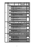
9.3.2 Reasons for Warning and Countermeasures
The following table lists the cause of the alarm and the treatment measures. If the fault cannot be cleared after
processing according to the following table, please contact our company.
Alarm number:
Alarm name
Reason
Confirmation method
The treatment measures
A.900
:
Position deviation is
too large
U, V, W wiring of servo motor is
incorrect
Confirm the connection of
servo motor main loop
cable.
Confirm whether the motor cable or encoder
cable has poor contact and other problems.
The gain of servo drive is low
Verify that the servo drive
gain is too low.
The servo gain is improved through automatic
adjustment (no-bit command) function, etc.
Position command acceleration is
too large
Try
to
reduce
the
commanded acceleration
before running.
Lower the position command acceleration. Or,
select the position command filter to smooth
the acceleration of the position command.
Relative to the operating conditions,
the alarm (Pn520) for excessive
position deviation is low
Confirm that the position
deviation is too large for
warning value (Pn520) is
appropriate.
Correctly set the value of parameter Pn520
Servo drive failure
-
Connect to the servo drive power supply
again. When an alarm still occurs, replace the
servo drive.
A.901
:
Excessive position
deviation
when
servo ON
The accumulated position deviation
during servo ON exceeds the
proportion set by (
Pn526×Pn528
100
)
-
When the servo ON is correctly set, the
warning value of position deviation is too large
(Pn528).
A.910
:
Overload
(Warning
before
becoming overload
alarm
(A.710
or
A.720))
Motor wiring, encoder wiring or poor
connection
Confirm wiring.
Confirm whether there is any problem with
motor wiring and encoder wiring.
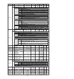
The operation of the motor exceeds
the
overload
protection
characteristic
Confirm
the
overload
characteristics
and
operation commands of
the motor.
Discuss load conditions and operating
conditions again.
Or reconsider the motor capacity.
The motor is not driven due to
mechanical factors, resulting in
excessive load during operation
Confirm
the
operation
command
and
motor
speed.
Improve mechanical factors.
Verify that the overload warning
value (Pn52B) is appropriate
Verify that the overload
warning value (Pn52B) is
appropriate.
Verify that the overload warning value (Pn52B)
is appropriate.
Servo drive failure
-
Replace the servo drive.
A.911
:
Vibration
Abnormal
vibration
in
motor
operation is detected
Confirm
the
abnormal
sound of the motor and the
speed
and
torque
waveforms
during
operation.
Reduce motor speed. Or reduce servo gain
through custom adjustment, etc.
The value of the moment of inertia
ratio (Pn103) is larger than the
actual value or varies greatly
Confirm the moment of
inertia ratio or mass ratio.
Correctly set the moment of inertia ratio
(Pn103).
Vibration detection value (Pn312 or
Pn384) is inappropriate
Verify that the vibration
detection value (Pn312 or
Pn384) is appropriate.
Set the vibration detection value (Pn312 or
Pn384) appropriately.
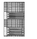
A.920
:
Regeneration
overload
(Warning
before
becoming
regeneration
overload (A.320))
Power supply voltage exceeds
specification range
Measure
the
supply
voltage.
Set the power supply voltage within the
specification
External regenerative resistance
value, servo drive capacity or
regenerative resistance capacity is
insufficient, or in a continuous
regenerative state
Reconfirm
operating
conditions and capacity.
Change the regenerative resistance value,
regenerative resistance capacity or servo drive
capacity. Adjust the operating conditions
again.
Continuously bears negative load
and is in continuous regeneration
state
Confirm the load applied to
the running servo motor.
Discuss
the
system
including
servo,
mechanical and operating conditions again.
A.921
:
DB overload
(Warning before DB
Overload (A.731))
The motor is being driven by
external force
Confirm operation status.
Do not drive the motor by external force.
The rotating or operating energy
when DB stops exceeds the
capacity of DB resistor
Confirm
the
usage
frequency of DB by DB
resistance
power
consumption.
Try the following measures.
Reduce the command speed of servo motor.
Reduce the moment of inertia or mass.
Reduce the number of DB stops.
Servo drive failure
-
Replace the servo drive.
A.930
:
Battery failure of
absolute encoder
The battery is not well connected
and not connected
Confirm
battery
connection.
Connect the battery correctly.
The battery voltage is lower than
the preset value (2.7 V)
Measure
the
battery
voltage.
Replace the battery.
Servo drive failure
-
Replace the servo drive.
A.960
:
MECHATROLINK
Communication
warning
The
communication
cable
of
MECHATROLINK
is
incorrectly
wired
Confirm the connection
status.
Connect MECHATROLINK communication
cable properly.
MECHATROLINK received data
incorrectly
due
to
mutual
interference
Confirm
the
setting
environment.
Take the following anti-interference measures.
• Adjust the wiring of communication cable and
FG to avoid interference.
• Install ferrite cores on communication cables.
Servo drive failure
-
Replace the servo drive.
A.971
:
Under voltage
AC power supply voltage driven by
servo is too low
Measure
the
supply
voltage.
Adjust the power supply voltage to the normal
range
Power supply voltage drops during
operation
Measure
the
supply
voltage.
Increase power supply capacity
Instantaneous
power
failure
occurred
Measure
the
supply
voltage.
If the instantaneous stop holding time (Pn509)
is changed, it is set to a smaller value.
Servo drive fuse blown
-
Replace the servo drive and connect the
reactor before using the servo drive.
Servo drive failure
-
Replace the servo drive.
A.97A
:
Command Warning
7
An unexecuted command was
received in the current layer
-
The command will be sent after the sending
condition is met.
A.97b
:
Out of Data Range
Out-of-range values are set in the
command data
Set the value within the set range in the
command data.
A.9A0
:
Overtravel
(Check
out
over-travel status
)
Overtravel detected in servo ON
The
status
of
the
over-travel
signal
is
confirmed through input
signal monitoring.
If the over-travel signal cannot be confirmed
through input signal monitoring, the over-travel
may be detected instantaneously. Carry out
the following projects.
• Do not execute commands from the upper
device to the over-travel field.
• Confirm the wiring of over-travel signal.


