background image

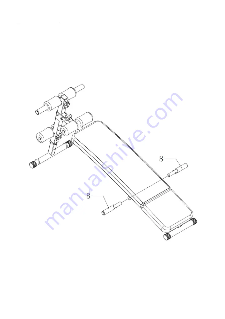
POSTUP MONTÁŽE - KROK 3


Do konstrukce hlavního rámu (1) vložte madla (8). 


Summary of Contents for L1110

Page 1: ...ŁAWKA WIELOFUNKCYJNA MULTIFUNKCIONAL BENCH LAVICE MULTIFUNKTIONALE BANK L1110 INSTRUKCJA UŻYTKOWANIA MANUAL INSTRUCTION NÁVOD K OBSLUZE GEBRAUCHSANWEISUNG ...

Page 2: ...pedały i siłowniki które ulegają najszybszemu zużyciu Uszkodzone części należy natychmiast naprawić lub wymienić do tego czasu nie wolno używać urządzenia do treningu 9 Nie wkładaj w otwory żadnych elementów 10 Zwracaj uwagę na wystające urządzenia regulacyjne i inne elementy konstrukcyjne które mogłyby przeszkadzać w trakcie ćwiczeń 11 Sprzęt wykorzystuj jedynie zgodnie z przeznaczeniem Jeśli któ...

Page 3: ...k 1 szt 3 Stopa przednia 1 szt 4 Dolne rolery piankowe 1 szt 5 Górne rolery piankowe 1 szt 7 Liny 2 szt 8 Uchwyty 2 szt 9 Śruba M10 75 2 szt 10 Pokrętło M 10 3 szt 11 Bolec zabezpieczający D8 55 1 szt 12 Śruba M10 55 2 szt 13 Nakrętka M10 1 szt ...

Page 4: ...rnik 2 Stopę przednią 3 Dolne rolery piankowe 4 Górne rolery piankowe 5dwie śruby M10 75 9 oraz dwa pokrętła M 10 10 Zamontuj wszystkie części tak jak pokazano na obrazku poniżej Ustaw je w dokładnym położeniu otworów i dokręć ...

Page 5: ...ij Ramę główną 1 jedno pokrętło M 10 10 dwie śruby M10 55 12 jedną nakrętkę M 10 bolec zabezpieczający D10 60 Zamontuj wszystkie części tak jak pokazano na obrazku poniżej Ustaw je w dokładnym położeniu otworów i dokręć ...

Page 6: ...MONTAŻ KROK 3 Wyjmij uchwyty 8 Zamontuj wszystkie części tak jak pokazano na obrazku poniżej Ustaw je w dokładnym położeniu otworów i dokręć ...

Page 7: ...MONTAŻ KROK 4 Wyciągnij uchwyt to mocowania linek 6 oraz dwie linki 7 Zamontuj wszystkie części tak jak pokazano na obrazku poniżej ...

Page 8: ...zgrzewka Ten etap pomoże przyspieszyć krążenie krwi co pozwoli na efektywniejsze ćwiczenie mięśni Poprawnie wykonana rozgrzewka zredukuje ryzyko kontuzji Wskazane jest rozciągnięcie ciała jak pokazano na rysunkach poniżej Każda z następujących czynności powinna być wykonywana przez co najmniej 30 sekund Nie rozciągaj się zbyt mocno jeśli poczujesz ból przestań naciągać mięśnie Mimo iż czynimy wsze...

Page 9: ...echowywania niewłaściwy montaż i konserwacja uszkodzenia i zużycie takich elementów jak linki paski elementy gumowe pedały uchwyty z gąbki kółka łożyska itp 6 Gwarancja traci ważność w przypadku Upływu terminu ważności samodzielnych napraw nieprzestrzegania zasad prawidłowej eksploatacji 7 Duplikaty karty gwarancyjnej nie będą wydawane 8 Produkt oddany do naprawy powinien być kompletny i czysty W ...

Page 10: ...tened 8 Always use the equipment as indicated If you find any defective components whilst assembling or checking the equipment or if you hear any unusual noise coming from the equipment while using stop Do not use the equipment until the problem has been rectified 9 Do not insert any object into any openings 10 Be aware of all regulation and constructions parts which may disturb during exercises 1...

Page 11: ...per support frame 1PCS 3 Front feet tube 1PCS 4 Foam set 1PSC 5 Top foam set 1PCS 7 Rope 2PSC 1 Pull up bar set 2PCS 9 Screw M10 75 2PCS 10 Knob nut M 10 3PCS 11 Safety hook D8 55 1PCS 12 Hexagon head screw M10 55 2PCS 13 Nut M10 1PSC ...

Page 12: ...r Support Frame 2 Front Feet Tube 3 Low Foam Set 4 Top Foam Set 5 two pieces of Cup Head Square Neck Screw M10 75 9 two pieces of Knob Nut M 10 10 Install them to the module Align them in the accurate hole position and tighten them ...

Page 13: ...ame 1 one piece of Knob Nut M 10 10 two pieces of Hexagon Head Screw M10 55 12 one piece of Nut M 10 one piece of Safety hook D10 60 Install them to the module shown in the picture Align them in the accurate hole position and tighten them ...

Page 14: ...ASSEMBLY STEP 3 Take out the multifunctional handle 8 Install it to the module shown in the picture B Align it in the accurate hole position ...

Page 15: ...uller 6 and install it to the module Align it in the accurate hole position Take out the two ropes 7 Install them to the module Align them in the accurate hole position and then you will finish the whole procedure of configuring the bench ...

Page 16: ...t period starts with a warm up We suggest you do the following exercise as the sketch map Each exercise at least about 30 seconds Even though we go to great efforts to ensure the quality of each product we produce occasional errors and or omissions do occur In any event should you find this product to has either a defective or a missing part Please contact us for a replacement Consumer service dep...

Page 17: ...correct assembly and maintenance damages and consumption of such elements as cables straps rubber parts pedals sponge grips wheels bearings etc 6 The guarantee expires in the event of expiry of the validity term self repairs failure to follow the rules of correct operation 7 No duplicates of the guarantee cards shall be issued 8 The product handed over for repair should be complete and clean If so...

Page 18: ...ozornost je třeba věnovat pedálům a motorům které podléhají opotřebení nejrychleji Poškozené části je potřeba ihned opravit nebo vyměnit Do té doby je užívání zařízení zakázáno 9 Nevkládejte do otvorů žádné předměty 10 Dávejte pozor na čouhající regulační části a jiné konstrukční části které by při tréninku mohly překážet 11 Zařízení využívejte pouze v souladu s jeho určením Jestliže bude některá ...

Page 19: ...LŮ 1 Hlavní rám 2 Vzpěra 3 Stabilizátor 4 Zarážka nohou 5 Horní zarážka 7 Expandér 2 ks 1 Madlo 2 ks 9 Šroub M10 75 2 ks 10 Ergonomická matice M 10 3 ks 11 Čep D8 55 1 ks 12 Šroub M10 55 2 ks 13 Matice M10 1 ks ...

Page 20: ...vory pro nastavení výšky a skrze jeden z nich protáhněte šroub M10x75 9 vložený do zarážky nohou 4 Šroub na druhé straně zajistěte ergonomickou maticí M10 10 Horní zarážku 5 připevněte pomocí šroubu M10x75 9 k vrchní části vzpěry 2 a zajistěte ergonomickýou maticí M10 10 ...

Page 21: ...vyloženého profile vzpěry 2 a díly spojte horizontálně pomocí šroubu M10x55 12 a matice M10 13 Pro zajištění lavice v pracovní poloze použijte čep 11 a konstrukci uzamkněte vložením svislého šroubu M10x55 12 a zajištěním ergonomickou maticí M10 10 ...

Page 22: ...POSTUP MONTÁŽE KROK 3 Do konstrukce hlavního rámu 1 vložte madla 8 ...

Page 23: ...POSTUP MONTÁŽE KROK 4 Gumové expandéry 7 zajistěte za oka stabilizátoru 3 ...

Page 24: ...Vám pomůže urychlit proudění krve což umožní efektivnější procvičení svalů Správně provedená rozcvička sníží riziko úrazu Je odporučeno provádět rozcvičku pomocí cviků níže zobrazených Každý z těchto cviků by měl být prováděn po dobu min 30 sekund Neprotahujte se příliš jestliže ucítíte bolest rozcvičku ukončete Přesto že děláme vše pro to abychom zajistili maximální kvalitu našich výrobků mohou s...

Page 25: ...ály držáky na houby kola ložiska atd 6 Záruka zaniká pokud vyprší její platnost bylo do produktu neodborně zasaženo nebyla dodržena pravidla řádné údržby 7 Duplikáty záručního listu nebudou vydány 8 Produkt dodaný do opravy by měl být kompletní a čistý v opačném případě má servis právo odmítnout přijetí produktu do opravy V případě dodání špinavého produktu může servis odmítnout jeho přijetí do op...

Page 26: ... erfüllt nur dann alle Sicherheitsbedingungen wenn es regelmäßig im Hinblick auf Verschleiß und Schäden überprüft wird Besonders wichtig ist es auf Pedale und Hydraulikzylinder zu achten die sich am schnellsten abnutzen Beschädigte Teile müssen sofort repariert oder ersetzt werden Bis diesem Moment darf dieses Gerät nicht verwendet werden 9 Keine anderen Elemente sollten in die Öffnungen eingeführ...

Page 27: ...ses Geräts beschädigen kann Stellen Sie das Gerät an einem trockenen Ort um es vor Feuchtigkeit und Korrosion zu schützen LISTE DER TEILE 1 Hauptrahmen 1 St 2 Stützrohr 1 St 3 Vorderer Standfuß 1 St 4 Griffe aus Schaumstoff unten 1 St 5 Griffe aus Schaumstoff oben 1 St 7 Expander 2 St 8 Handgriffe 2 St 9 Schraube M10 75 2 St 10 Drehknopf M 10 3 St 11 Verriegelungsbolzen D8 55 1 St 12 Schraube M10 ...

Page 28: ...zwei Griffe aus Schaumstoff 4 und 5 zwei Schrauben M10 75 9 und zwei Drehknöpfe M 10 10 heraus Montieren Sie alle Teile so wie auf der unten stehenden Abbildung gezeigt wurde Achten Sie auf die richtige Position der Elemente in den Öffnungen und ziehen Sie alles fest an ...

Page 29: ...M 10 10 zwei Schrauben M10 55 12 eine Mutter M 10 einen Verriegelungsbolzen D10 60 heraus Montieren Sie alle Teile so wie auf der unten stehenden Abbildung gezeigt wurde Achten Sie auf die richtige Position der Elemente in den Öffnungen und ziehen Sie alles fest an ...

Page 30: ...TT 3 Nehmen Sie die Handgriffe 8 heraus Montieren Sie alle Teile so wie auf der unten stehenden Abbildung gezeigt wurde Achten Sie auf die richtige Position der Elemente in den Öffnungen und ziehen Sie alles fest an ...

Page 31: ...MONTAGE SCHRITT 4 Nehmen Sie den Griff zur Montage der Expander 6 und zwei Expander 7 heraus Montieren Sie alle Teile so wie auf der unten stehenden Abbildung gezeigt wurde ...

Page 32: ...r gesunden Ernährung Aufwärmphase Diese Etappe dient der Verbesserung Ihrer Durchblutung und der Muskelleistung sowie der Verringerung des Risikos von Verletzungen Es wird Ihnen empfohlen die auf der Abbildung dargestellten Aufwärmübungen zu machen Jede Übung soll circa 30 Sekunden lang gemacht werden Sie sollten die Muskeln nicht überdehnen oder überfordern Wenn Sie Schmerzen haben unterbrechen S...

Page 33: ...scht nach Ablauf der Haltbarkeit bei freiwilligen Reparaturen Nichteinhaltung der Regeln für den ordnungsgemäßen Betrieb 7 Duplikate der Garantiekarte werden nicht ausgestellt 8 Das zu reparierende Produkt sollte vollständig und sauber sein Bei Feststellung von Mängeln ist der Service die Annahme zur Reparatur zu verweigern Im Falle der Lieferung eines verschmutzten Produkts kann der Service die A...

Reviews: