


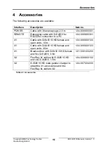


Connections
Copyright HMS Technology Center
Ravensburg GmbH
7
FRC-EP170 Manual, Version 1.3
2.2
Ethernet connector (ETHERNET)
The Ethernet interface is implemented as a standard Ethernet RJ45.
The Ethernet interface is galvanically isolated from the other interfaces.
2.3
USB device connector (USB-B)
The USB connector is used as a USB device interface to a PC. It is
implemented as a standard USB B type.
The USB interface is not galvanically isolated due to system
constraints, so this interface must be used with corresponding care.
Always provide a grounded connection between your test object and
the FRC-EP170 before connecting the PC to the FRC-EP170 via
USB. Otherwise, a compensation current can flow between the test
object and the PC through the USB connection, which under some
circumstances can damage the PC.
2.4
USB host connector (USB-A)
The USB connector is used to connect USB devices to the FRC-EP170 It is
implemented as a standard USB A type.
2.5
SD card slot
The SD card slot can work with all current SD and SDHC cards. The SD card
slot has a push-push mechanism. To insert the card, push the card until it
stops, at which point you hear and feel a click. The card is then held on its
own. To remove the card, press the card to the stop again.
The holding mechanism releases and the card can be pulled out.
2.6
Displays
On the front of the unit there are eight LEDs that can be used to read off the
device and communications status.
8
7
6
5
4
3
2
1
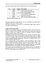
Summary of Contents for FRC-EP170
Page 1: ...Hardware Manual FRC EP170 Automotive Platform ...
Page 22: ......


