


Anybus X-gateway Module Description
1-5
© 2012 HMS Industrial Networks AB
Doc.Id. HMSI-168-25
Hardware Description
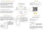
The Anybus X-gateway J1939 to Modbus Interface has a 15-pin D-Subminiature
connector for power and network connections. This connector has pins for module
power, J1939 CAN connections, and Modbus RS-485 connections. See “Installa-
tion” Page 2-1 for details on using this connector.
A 25-pin D-Subminiature connector is provided for connection to a PC running
the Anybus Configuration Tool. This is a standard RS-232 DTE connection and
will require a null-modem cable (pins 2 and 3 swapped) to connect the module to
a PC serial port or USB serial adapter. See “Installation” Page 2-1 for details on
using this connector.
The front of the module has a set of 3 LEDs that are used for status indication.
These LEDs provide visual status for the overall module, the J1939 interface, and
the Modbus interface. See “Status and Diagnostics” Page 7-1 for details on how
the LEDs are used.
The back of the module has a DIN rail mount to allow the module to be mounted
on a DIN rail.