


Intesis
TM
Modbus Server
– Mitsubishi Heavy Industries AC
User’s Manual r1.0 eng
© HMS Industrial Networks S.L.U - All rights reserved
This information is subject to change without notice
URL https://www.intesis.com
22 / 26
Troubleshooting
If Intesis
TM
is not working properly or even not working at all, please check the following
conditions to be accomplished.
5.3.1
Physical checking
First point to look at to make sure that Intesis
TM
is not working properly is to check physical
connections:
1.- Make sure that the power plug is correctly connected and current is available in
the power line.
2.- Check Intesis
TM
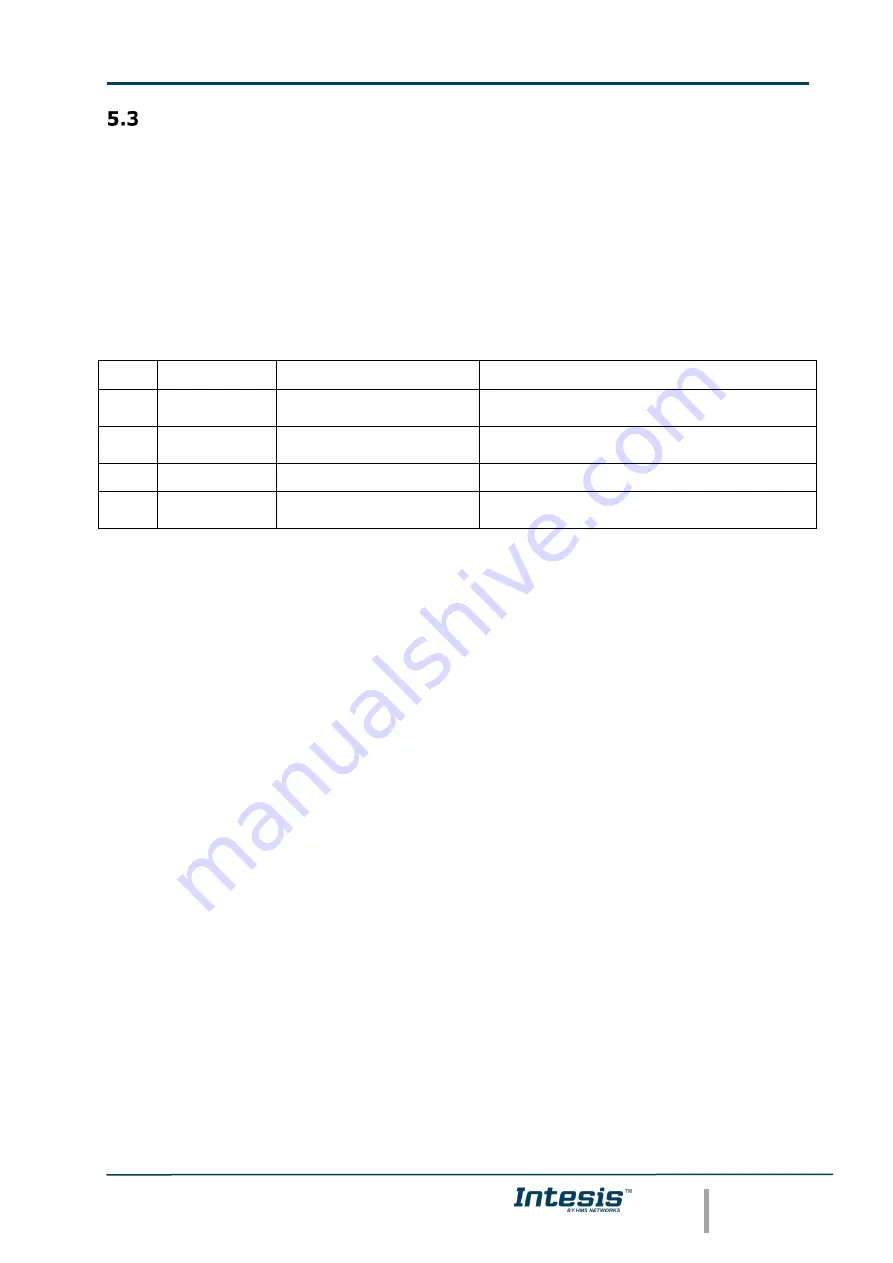
LED status:
LED
Status
Explanation
Solution
OP
Off
No power reaching the
internal device
Check power connection
Check fuse status
(see 13 in Figure 3.2)
ERR
Blinking once
perdiodicaly
Superlink
communication failure
Check Superlink cables and terminals
(connectors, length of cables, etc.)
HOST
Off
Configuration error
Download the binary file again
(see 4.3)
PAC
Off
Communication error in
the Superlink network
Check the Mitsubishi Heavy Industries
Superlink network and its connections
Table 5.1
Intesis
TM
LED status information
5.3.2
Software checking
Once physical connections have been checked, if functioning problems still remain, please
use the LinkBoxMB tool to monitor the working status of the device.
•
To check the Modbus communication status, click on the
Modbus
button in the
menu bar
(see Figure 4.1).
•
To check the MHI communication status, click on the
MHI
button, also in the
menu bar
(see Figure 4.1).
•
To check the signal values in the Modbus registers, click on the
Signals
button,
also in the
menu bar
(see Figure 4.1).
Further information regarding the monitoring procedure and the information provided in
each window can be consulted in the LinkBoxMB Manual.