background image

28

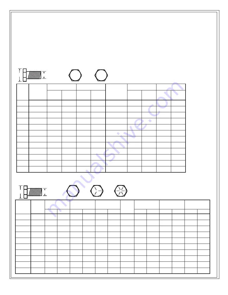
Bolt Torque Table

B

A

B

A

8.8

10.9

SAE 2

SAE 5

SAE 8

These table

s

 are offered as the suggested maximum torque values for dry (not lubricated) threaded products and 

are only a general guide. 

Check tightness of bolts periodically, replace hardware with the same strength bolt.

Torque specification for bolts are identified by their head markings as shown.

See the “Wheel Torque Specification” page for wheel bolt /nut torque settings

METRIC TORQUE SPECIFICATIONS

SAE TORQUE SPECIFICATIONS

N-m

lbs-ft

N-m

lbs-ft

N-m

lbs-ft

N-m

lbs-ft

10 mm

6 x 0.75

---

---

---

---

6 x 1.0

11.3

8.3

16.5

12.2

13 mm

8 x 1.0

27

20

38

28

8 x 1.25

27.3

20.1

40.1

29.6

16 mm

10 x 1.25

52

38

73

54

10 x 1.5

54

40

49

36

18 mm

12 x 1.25

95

70

135

100

12.1.75

93

69

137

101

21 mm

14 x 1.5

150

111

210

155

14 x 2.0

148

109

218

161

24 mm

16 x 1.5

225

166

315

232

16 x 2.0

230

170

338

249

27 mm

18 x 1.5

325

240

460

339

18 x 2.5

329

243

469

346

30 mm

20 x 1.5

460

339

640

472

20 x 2.5

464

342

661

487

34 mm

22 x 1.5

610

450

860

634

22 x 2.5

634

468

904

667

36 mm

24 x 2.0

780

575

1100

811

24 x 3.0

798

588

1136

838

41 mm

27 x 3.0

---

---

---

---

27 x 3.0

1176

867

1674

1234

46 mm

30 x 2.0

---

---

---

---

30 x 3.0

1597

1178

2274

1677

Class 10.9

Class 8.8

Wrench 

Size:

"A"

 Thread Size: 

"B" 

Fine

 Thread Size: "B" 

Coarse

Class 10.9

Class 8.8

lbs-ft

.

N-m

lbs-ft

N-m

lbs-ft

N-m

lbs-ft

N-m

lbs-ft

N-m

lbs-ft

N-m

7/16”

1/4-28

6

8.1

10

13.6

14

19.0

1/4-20

5

6.8

8

10.8

12

16.3

1/2”

5/16-24

13

17.6

19

25.7

27

36.6

5/16-18

11

14.9

17

23.0

25

33.9

9/16”

3/8-24

23

31.2

35

47.4

49

66.4

3/8-16

20

27.1

31

42.0

44

59.6

5/8”

7/16-20

36

48.8

55

74.5

75

101.6

7/16-14

32

43.4

49

66.4

70

94.9

3/4”

1/2-20

55

74.5

85

115.2

120

162.6

1/2-13

49

66.4

75

101.6

107

145.0

13/16”

9/16-18

79

107.0

122

165.3

172

233.1

9/16-12

70

94.9

109

147.7

154

208.7

15/16”

5/8-18

110

149.1

170

230.4

240

325.2

5/8-11

97

131.4

150

203.3

212

287.3

1-1/8”

3/4-16

192

260.2

297

402.4

420

569.1

3/4-10

173

234.4

266

360.4

376

509.5

1-5/16”

7/8-14

184

249.3

474

642.3

668

905.1

7/8-9

166

224.9

429

581.3

606

821.1

1-1/2”

1.0-12

274

371.3

705

955.3

995

1348.2

1.0-8

250

338.8

644

872.6

909

1231.7

SAE 8

SAE 2

SAE 5

SAE 8

Wrench 

Size:

"A"

 Thread 

Size: "B" 

Fine

 Thread 

Size: "B" 

Coarse

SAE 2

SAE 5

Summary of Contents for BK48LF

Page 1: ...erate the equipment without thoroughly reviewing this manual for safe and proper operation Rev 171019 HA00100 BK Ba Operator s Manual Keep this manual with the machine at all times PRINTED IN CANADA BK Series Bale Knife BK48LF BK60LF BK72LF CAUTION Operational Hazard Personal Protection Equipment PPE is required when operating or maintaining this machine SNL00001 ...

Page 2: ...2 Notes ...

Page 3: ...6 Bumper Assembly 16 Wrap Undresser 16 Storage Stand 16 Wrap Grabber 16 Check Valve 17 Kverneland Tines 17 Hardened Cutting Knives 17 Initial Setup 18 Hydraulics 18 Mount the Bale Knife 19 Remove Shipping Clamps 19 Adjust the Bumper BK60 72 only 19 Adjust the Undresser 20 Test 20 Field Operation 21 Operation Safety Checklist 21 Prepare 21 Material 21 Mount the Blade Knife 22 Quick Attach 22 Hydrau...

Page 4: ...steel cutting knives eight on the BK48 60 nine on the BK72 deliver a consistent cut and stay sharp If any knife is damaged the bolt on feature allows for easy replacement of a single knife without needing to replace the entire row The upward slicing design allows for bales to be sliced not only into feeders and mixers but also as little as 6 above the ground making it ideal for operation in tight ...

Page 5: ... rear as mentioned throughout this manual are determined when sitting in the power unit driver s seat and facing in the direction of travel Intended Use The HLA BK series Bale Knife is intended for attachment and use on qualified power units for the purpose of handling round bales slicing bale net and plastic wrapping and feeding round bales Parts List The parts lists and hydraulic schematics for ...

Page 6: ... WARNING Pinch Point Hazard The top rail and beam form a poten tial pinch point be aware of where hands and feet are while adjusting the top rail SL00002 Safety Label Safety Alert Safety Hazard Safety Term Safety Hazard Explanation Safety The safety information given in this manual does not replace any safety codes insurance needs government and local laws DANGER Indicates an imminently hazardous ...

Page 7: ...this manual Read and understand the safety labeling which appears on the implement Have a first aid kit available for use should the need arise and know how to use it Pay attention to the job at hand Do not let your mind lose concentration on what you are doing No accident prevention program can be successful without the wholehearted cooperation of the person who is directly responsible for the op...

Page 8: ...nual and have developed a thorough understanding of the safety precautions and of how it works Review the safety instructions with all users annually 6 If the elderly are assisting with work their physical limitations need to be recognized and accommodated Assistants should be a responsible properly trained and physically able person familiar with machinery and trained in this implement s operatio...

Page 9: ... between the towing unit and the machine 4 Do not permit riders while transporting this machine 5 Where possible avoid operating near ditches embankments and holes 6 Lifting heavy loads overhead while traveling may decrease your power units stability Loss of control could lead to serious personal injury 7 Check the power units owner manual to determine if a counter weight is required 8 Tractors sh...

Page 10: ...attention immediately Serious infection or toxic reaction can develop from hydraulic fluid piercing the skin surface 6 Relieve pressure on hydraulic system before maintaining or working on system 7 All hydraulic work must be done by qualified personnel Safe Work Not all work spaces are the same but the principles presented here can be applied to any work space Survey the work site remove debris an...

Page 11: ... important safety device on this equipment is an informed SAFE operator Caution be aware of sharp cutting arm blades and tines Cutting arm must aways be stored in the up position Use caution and keep distance when walking around the blades and tines Possible tripping hazard could result in death or serious injury from laceration or impact Caution Moving parts present a potential pinch hazard and c...

Page 12: ... illustrated however label locations are similar for all models unless otherwise indicated Good safety practice requires that you familiarize yourself with the label and the safety message it is delivering Be aware of the equipment or particular equipment feature that requires your SAFETY AWARENESS SL00022 SL00009H SL00008 SL0010H SL00009H SL00015 SL00004 SNL00001 SL0010H SL00008 SL00022 SL00002 S...

Page 13: ... 122 cm 183 cm 48 72 182 9 cm 4 5 x 12 0 213 4 cm 4 5 x 14 0 243 8 cm 4 5 x 16 0 n a 30 5 cm 12 Adjustment range 61 cm 24 Adjustment range 8 8 9 Bale Knife Model Kverneland Tines Bail Wrap Grabber Individually Replaceable Hardened Cutting Knives 75 l min 20 gpm Minimum Hydraulic Flow Recommened Power unit size Weight Mounting Not Recommended Quick attach frame Round Bail Capacity diameter Hydrauli...

Page 14: ... Inspection Before putting the BK series bale knife into service the first time inspect the machine for shipping damage If damage does exist do not use Notify your dealer immediately to have damaged parts replaced or repaired WARNING Pinch Point Hazard Caution do not detach or store the bale knife horizontal position without attaching it to the shipping storage stand serious injury could result SL...

Page 15: ... efficiency By following instructions in conjunction with a good maintenance program your BK bale knife will provide many years of trouble free service Do not operate this machine if you are not familiar with its features The BK72 is illustrated below showing its basic components and features Components and features are similar for the entire BK series unless noted Review the various components an...

Page 16: ...ntaining this machine SNL00001 Storage Stand All Bale Knife models are shipped with a convenient storage stand Use the storage stand to place your bale knife in when not in use The stand helps to stabilize the bale knife for safe storage and can be easily moved using a lift fork on you power unit CAUTION Operational Hazard Be aware of sharp cutting arm blades and tines Cutting arm must aways be st...

Page 17: ... once hydraulic pressure is applied Kverneland Tines Each BK is equipped with seven Kverneland straight conus 1 32 tines Kverneland tines are heat treated resulting in a tough tine with superior bale penetration Ideal for bale handling chores to the feed site Hardened Cutting Knives The Bale Knife cutting arm assembly features hardened knife blades to easily cut through bale wrap The bolt on knive...

Page 18: ...sible mid mount loader valve etc and is up to the customer See your power unit manual on how to operate your auxiliary hydraulics Caution only qualified personnel should make modifications and connections to the power units hydraulic system The hydraulic hoses must be Good quality 3000 psi max Sufficient length to reach the auxiliary ports 3 8 i d minimum BK end of the hose must have 1 2 NPT fitti...

Page 19: ...hipped it is bolted to the shipping storage stand Remove the two clamps as shown CAUTION Operational Hazard Always ensure the quick attach locks or pins are engaged An unsecured bale knife could slip out of the quick attach WARNING Pinch Hazard Keep hands away from mounting points while attaching to the power unit Potential pinch hazards exist between the bale knife and power unit SL00022 Shipping...

Page 20: ...out warning Do not check for leaks with your hand or fingers while the system is pressurized SL00015 Adjust the Undresser Ensure the power unit engine is off and cutting arm is in the up position Carefully remove all the nuts and bolts Adjust the assembly to the position required for your bale size move it out for smaller bales in for larger Replace tighten and torque the bolts see torque chart If...

Page 21: ...t or sides of the machine Falling objects are a potential hazard 9 9 Drive slow and carry low Clear the area of bystanders especially small children Training each operator must be trained and familiar with the set up and operation of the product and its components Review Components and Features Operation Safety Checklist Power unit safe operating instructions It is recommended that each person wea...

Page 22: ...d operating instructions for your power unit Connect the BK hydraulic hoses to the power units auxiliary hydraulic connectors Ensure the connection is secure and the hoses are free to move without snagging Auxiliary hydraulic connectors BK hydraulic hoses CAUTION Operational Hazard Always ensure the quick attach locks or pins are engaged A unsecured bale knife could slip out of the quick attach WA...

Page 23: ...same time lift the loader arms as you back away Keep the bale low and continue on to the feeding site Carefully set the bale on the ground and position it at 90 to the feed area Feeding the Bale This process describes how to load the bale into a mixer however the process will be similar for any feed area Open the cutting arm to the bottom keeping the hydraulics activated until the wrap grab is ful...

Page 24: ...he BK added stability when in storage 3 The BK should be stored with the cutting arm face side against a wall to prevent potential head injury from walking under the cutting arm 4 Thoroughly wash the machine with a pressure washer or water hose to remove all dirt mud or debris 5 Remove all remaining material and debris from the machine 6 Inspect for damaged or worn parts Repair or replace before n...

Page 25: ...d Tighten any fitting that is leaking Ensure fittings are clean and free of dirt Hydraulic Oil Hydraulic oil is an important part of your BK Monitoring your hydraulic oil will prevent hydraulic failures and result in long lasting equipment with good performance Hydraulic oil level in the power unit should be checked daily and the quality of the oil should be inspected every 50 hrs If the oil is di...

Page 26: ...ymbol indicates a grease zerk location shown in the illustrations below Lubricate with an good Lithium EP2 grease or equivalent Use a hand held grease gun for all greasing one shot of grease is adequate Wipe grease zerk with a clean cloth before greasing to avoid injecting dirt and grit Replace any broken zerk fittings immediately If grease zerk will not take grease remove and clean thoroughly Als...

Page 27: ...g may be required to loosen it from the frame Insert the new tine replace the M20 nut ensure the nut taper is towards the frame Torque the taper nut to 290 325 ft lb ft lbs Sharpening Gloves should always be used when sharpening the blades and extreme care be taken while working around the blades Inspect the blades for damage and repair if possible Blades may be sharpened in place on the cutting a...

Page 28: ...50 860 634 22 x 2 5 634 468 904 667 36 mm 24 x 2 0 780 575 1100 811 24 x 3 0 798 588 1136 838 41 mm 27 x 3 0 27 x 3 0 1176 867 1674 1234 46 mm 30 x 2 0 30 x 3 0 1597 1178 2274 1677 Class 10 9 Class 8 8 Wrench Size A Thread Size B Fine Thread Size B Coarse Class 10 9 Class 8 8 lbs ft N m lbs ft N m lbs ft N m lbs ft N m lbs ft N m lbs ft N m 7 16 1 4 28 6 8 1 10 13 6 14 19 0 1 4 20 5 6 8 8 10 8 12 ...

Page 29: ...ic fluid generally indicated by foamy appearance of fluid Low hydraulic fluid level Check and refill hydraulic system to proper level Hydraulic fluid foaming due to improper hydraulic oil usage Refer to Power Unit s manual and replace hydraulic oil using recommended hydraulic oil Hydraulic oil heating Dirty oil Drain and refill oil replace filter Partially plugged inlet filter Clean filter element...

Page 30: ...30 Accessories For accessories or replacement parts call your dealer for pricing and availability or go to hlaattachments com and click on Parts ...

Page 31: ...4 D DANGER 6 H High Pressure Hazard 18 20 22 25 Hydraulic connection 18 hydraulic hoses 18 Hydraulic Oil Hazard 25 I IMPORTANT 6 K KEY TO SAFETY 7 L locks or pins 22 O Operator 10 P prevent premature wear 26 R referred to as 4 relieve pressure 24 25 ROPS 9 21 23 S safety message box 6 Safety Training 8 U Untrained operators 21 W WARNING 6 Workers 10 ...

Page 32: ...32 HORST WELDING 8082 Rd 129 Listowel ON N4W 3G8 Canada 519 291 4162 1 866 567 4162 Fax 1 519 291 5388 sales horstwelding com www horstwelding com ...

Reviews: