


H
H
L
L
-
-
S
S
e
e
r
r
i
i
e
e
s
s
E
E
l
l
e
e
c
c
t
t
r
r
i
i
c
c
A
A
c
c
t
t
u
u
a
a
t
t
o
o
r
r
I
I
n
n
s
s
t
t
a
a
l
l
l
l
a
a
t
t
i
i
o
o
n
n
a
a
n
n
d
d
O
O
p
p
e
e
r
r
a
a
t
t
i
i
o
o
n
n
M
M
a
a
n
n
u
u
a
a
l
l
H
H
K
K
C
C
16
4.4
Force Switch Setting
Force spring which detects the variation of force during operation is installed for preventing damage of valve and actuator
under overload condition. Once actuator is under overload, force switch is tripped and actuator stoped immediately.
The force switches are set by manufacturer on the production site basically.
Re-setting be necessary, please contact the HKC service or representative before setting.
Caution ;
Do not reset force switch to a setting higher than the maximum recommended by the manufacturer.
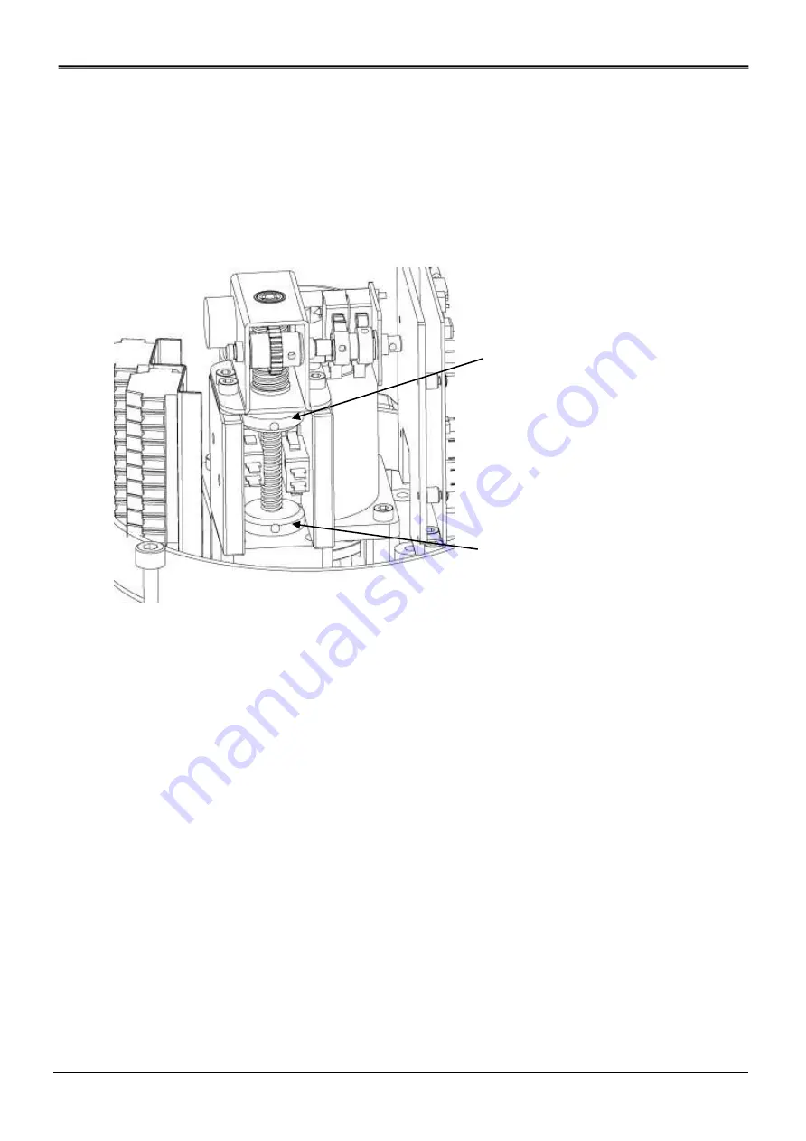
Open force switch & cam(RED Color)
Close force switch & cam (BLUE Color)
4.5
Position Feedback Potentiometer (Optional)
4.5.1
Calibration Potentiometer
The potentiometer has been calibrated at the factory. However, if re-calibration is required, proceed as follows:
Apply power (or use manual override) to drive the actuator to its true closed position (clockwise rotation).
Connect an ohmmeter to P1 (red) and P3 ( black ) resistance should be approximately 1000ohms
Put actuator full close(down) position.
Loosen the point shaft gear and connect the ohmmeter to P1 (red) and P2 (white) and gently rotate until a reading
of 80-120
Ω
is achieved (100 ohms preferred).
{Full close range: 0~100
Ω
Full open range:700~900
Ω
}
While maintaining this reading tighten the point gear set screw with an hex wrench(HL5,7KN).
Engage potentiometer spring between gear and pointer shaft (refer diagram B)