43
D 1
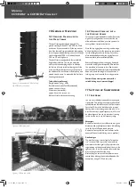
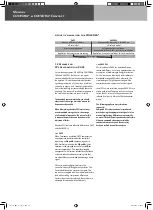
Figure 19: Attaching the lashing strap
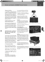
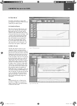
Figure 19: Example fixed mode application with 4.5° angle
Hoist the COHEDRA
®
Compact array with the eight
enclosures just high enough to remove it from
the case.
Insert the pins on the back of the bottom four
enclosures’ Set Angle holes to achieve the desired
curving angle. Connect the remaining speaker cords.
Repeat the above procedure to configure even more
CDR 108 enclosures in a flown stacked array.
Raising the System
The enclosures are rigged, speaker cords are all
connected, and the pins are set in the required
configuration. If you want to use the lashing strap
to curve the COHEDRA
®
Compact array, connect
one of its hooks to the rigging frame. Using a
shackle (an 8-mm bolt), attach the hook on the
other end to the bottom bin (best to the connector
component).
Tighten the strap until it exerts enough force to
curve the array as desired.
Once you have hoisted the COHEDRA
®
Compact
array, secure it against gusts of wind or accidental
twisting using two lashing straps or ropes.
4.2 Fixed Mode
To determine the splay between two enclosures in
fixed mode, you must insert one pin (Set Angle) and
fix the connector component in place with the second
pin. To fix the selected angle, insert the pin into the
neighboring hole labeled Link above the selected
angle (Set Angle). This fixes the connector component
in place so that it is immobile in all directions (See
Fig. 20).
This option gives you the same splay options between
two CDR 108 C enclosures to choose from – that is,
angles of 0°, 1.5°, 3°, 4.5°, 6°, 7.5° and 9°.
To set up the system, follow the same procedure
described for compression mode. Often when arrays
are sharply curved it becomes difficult to rig additional
blocks. In this event, you must mount enclosures
separately from below.
Rigging and Curving COHEDRA
®
Compact System
co_coco_BDA_de_engl_2.indd 43
18.09.2006 17:09:11


