8.2.5
Water filling
1
Check that a water check valve (ATW-WCV-01 accessory)
with a shut-off valve (field supplied) is connected to the
water filling point (water inlet connection) for filling the space
heating hydraulic circuit (see
“8.2 Space heating and DHW”
).
2
Make sure all the valves are open (water inlet/outlet shut-off
valves and the rest of valves of the space heating installation
components).
3
Ensure that the air purgers of the unit and installation are
open (turn the unit air purger twice at least).
4
Check that the drain pipes connected to the safety valve
(and to the drain pan in case of installing the “Cooling kit”
accessory) are correctly connected to the general draining
system. The safety valve is later used as an air purging
device during the water filling procedure.
5
Fill the space heating circuit with water until the pressure
displayed on the manometer reaches approximately 1.8 bar.
?
N O T E
While the system is being filled with water, it is highly recommended
to operate the safety valve manually so as to help with the air purging
procedure.
6
Remove as much air from inside the water circuit as possible
through the air purger and other air vents in the installation
(fan coils, radiators...).
7
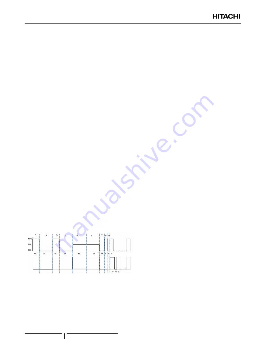
Start the air purge procedure test. There are two modes
(Manual or Automatic) which helps in case of installations
with heating and DHW operation:
a.
Manual: Start and stop the unit manually using the unit
controller (Run/Stop button) and also using the DSW4
pin 2 of the PCB1 (ON: Forced to derive to DHW coil;
OFF: Forced to derive to space heating).
b.
Automatic: Select the air purge function using the
user controller. When the automatic air purge function
is running, the pump speed and the position of the
3-way valve (space heating or DHW) are automatically
changed:
Water
pump
DHW
3Wv
Seconds
Seconds
Repeat...
Repeat...
ON
OFF
8
If a little quantity of air is still remaining in the water circuit,
it will be removed by the automatic air purger of the unit
during the first hours of operation. Once the air in the
installation has been removed, a reduction of water pressure
in the circuit is very likely to occur. Therefore, additional
water should be filled until water pressure returns to an
approximate level of 1.8 bar.
?
N O T E
• The unit is equipped with an automatic air purger (factory supplied) at
the highest location of the unit. Anyway, if there are higher points in
the water installation, air might be trapped inside water pipes, which
could cause system malfunction. In that case, additional air purgers
(field supplied) should be installed to ensure no air enters into the
water circuit. The air vents should be located at points which are
easily accessible for servicing.
• The water pressure indicated on the unit manometer may vary
depending on the water temperature (the higher temperature, the
higher pressure). Nevertheless, it must remain above 1 bar in order
to prevent air from entering the circuit.
• Fill in the circuit with tap water. The water in the heating installation
must comply with EN directive 98/83 EC. Non-sanitary controlled
water is not recommended (for example, water from wells, rivers,
lakes, etc.) (See
“Water quality”
section at the CD-ROM).
• The maximum water pressure is 3 bar (nominal opening pressure of
the safety valve). Provide adequate reduction pressure device in the
water circuit to ensure that the maximum pressure is NOT exceeded.
•
For heating floor system, air should be purged by means of an external
pump and an open circuit to prevent the formation of air pockets.
• Check carefully for leaks in the water circuit, connections and circuit
elements.
DRAIN PIPING
PMML0342B rev.1 - 03/2016
14


