Chapter 3. Component Names and Functions
3-7
Ch
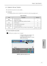
a
pt
e
r 3.
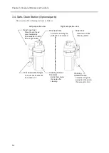
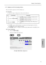
3.3. Print Head
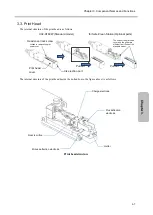
The internal structure of the print head is as follows.
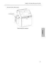
UX2-D160W (Standard model)
for Safe-Clean Station (Optional parts)
The internal structure of the print head (inside the dotted box in the figure above) is as follows.
Print head structure
Head cover lock screw
Loosen to remove the print
head cover.
Print head
cover
Pull out
Pull out
The ends of the print head
cover and the gutter are
different from those of the
standard model.
Ink ejection port
Charge electrode
Nozzle orifice
Plus deflection
electrode
Gutter
Minus deflection electrode
Summary of Contents for UX2 Series
Page 6: ......
Page 14: ......
Page 17: ...iii ...
Page 24: ......
Page 37: ...2 1 Chapter 2 2 Specifications Chapter 1 Chapter 2 Chapter 3 Chapter 4 Chapter 5 ...
Page 41: ......
Page 42: ...This page is blank ...
Page 53: ......
Page 54: ...This page is blank ...
Page 82: ......
Page 118: ......
Page 156: ...This page is blank ...
Page 205: ...Chapter 7 Auxiliary Functions 7 49 Chapter 7 HOME screen after editing widget ...
Page 206: ...This page is blank ...
Page 228: ...This page is blank ...
Page 247: ......
Page 248: ...This page is blank ...
Page 258: ...This page is blank ...
Page 276: ...This page is blank ...
Page 292: ......
Page 293: ...13 1 Chapter 13 13 Troubleshooting Guide Chapter 13 Chapter 11 Chapter 12 Chapter 14 Appendix ...
Page 296: ...This page is blank ...
Page 297: ...14 1 Chapter 14 14 Emergency Procedures Chapter 14 Chapter 11 Chapter 13 Chapter 12 Appendix ...
Page 299: ......
Page 300: ......


