


41
SETUP OPERATION (continued)
Viewing Images from a PC (continued)
Setting Picture Adjustment (continued)
w
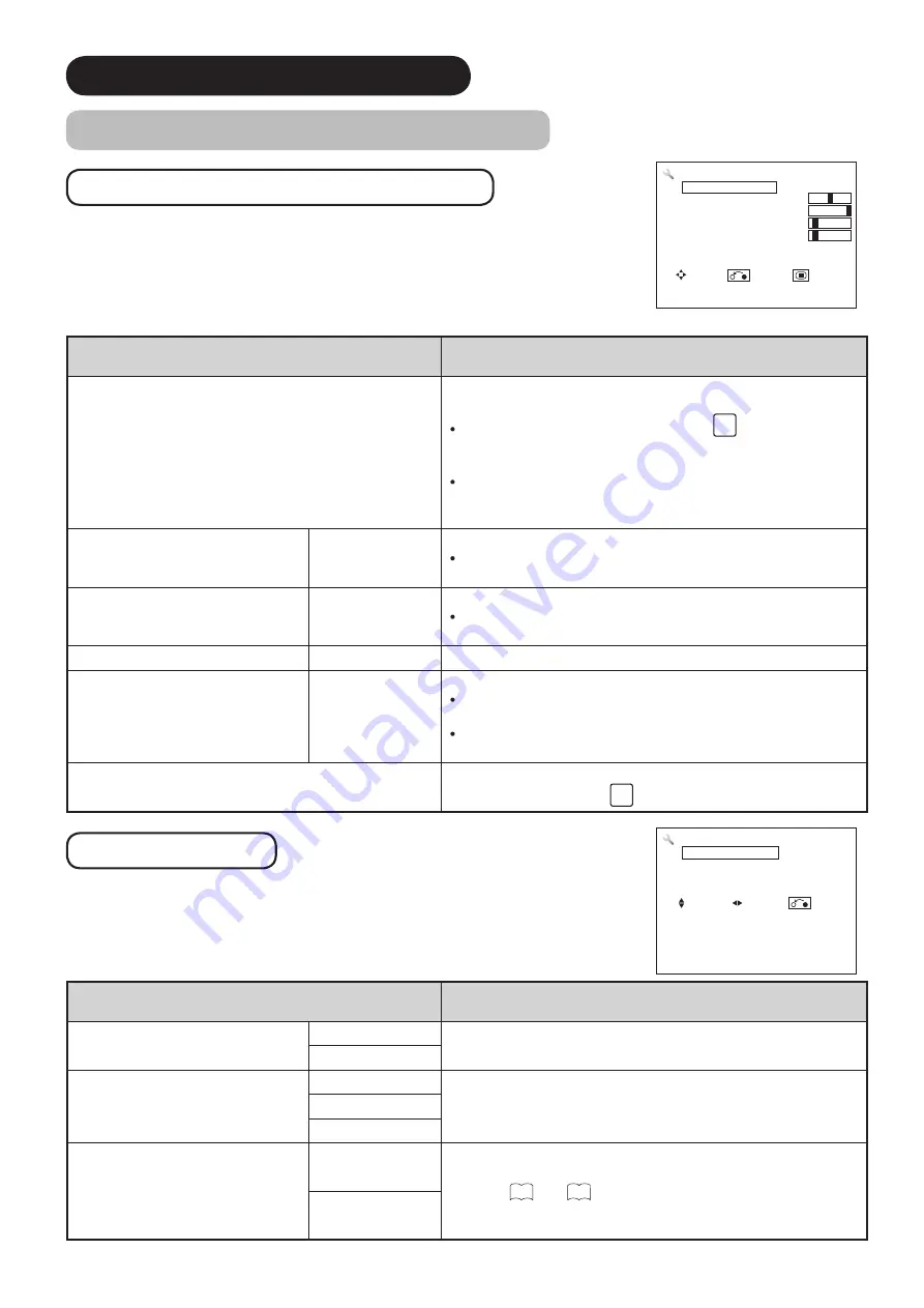
Setup Menu
Select
“Setup”
from the Menu list.
Selected Items
Setup hint
Auto Adjust
Adjusts Horizontal Position, Vertical Position, Horizontal
Clock, and Clock Phase automatically.
Select "
Adjust
" then press the
OK
button to start
automatic adjustment as necessary. The message “Auto
Adjusting” is displayed.
The image might not be adjusted to its optimum condition
depending on the types of signals. In that case, adjust
each item manually.
Horizontal Position
-63~+63
Adjusts the display position horizontally.
When the value exceeds a possible range, it will be
displayed in magenta.
Vertical Position
-31~+31
Adjusts the display position vertically.
When the value exceeds a possible range, it will be
displayed in magenta.
Horizontal Clock
-31~+31 Minimizes vertical stripes on the screen.
Clock Phase
0~+63
Minimizes the blurring of letters and stripes on horizontal row.
Be sure to adjust Horizontal Clock before adjusting Clock
Phase.
When the value exceeds a possible range, it will be
displayed in magenta.
Reset
Each item in Setup Menu can be restored to the factory
setting by pressing the
OK
button.
Advanced Setting
Select
“Setup”
from the Menu list and skip to the second page.
Selected Items
Setup hint
Frequency Display
Off Set to On for PC signal frequency information to be
displayed on the Input Signal Screen Display.
On
WXGA Mode
Off
Selects the resolution when a WXGA signal is received.
1280X768
1360X768
RGB Input
RGB Selects the effective signal.
Refer to
26
and
40
for details.
Composite
Setup
Auto Adjust
Adjust
Horizontal Position 0
Vertical Position +31
Horizontal Clock –20
Clock Phase +10
Reset
Reset
Select Return Exit
Setup
Frequency Display
Off
WXGA Mode
Off
RGB Input
RGB
Select On/Off Return