background image


4-40


Chapter 4 

Safety  Function 


4.7.2

 Release of SBC control signal 

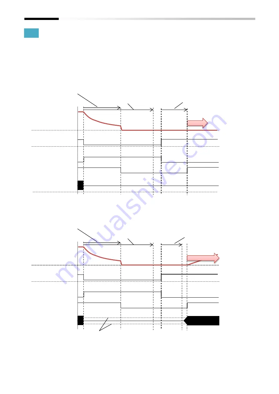
Time chart of release of SBC state is shown as below. 


Timing chart 

e.g. Case: SBC-A after STO-A,   
[1-31]SBC-A Time linkage=00(SBC after STO), 
[1-12]STO-A Release Mode =01(With safety signal) and   
[1-36]SBC-A release level =0.00%: 


e.g. Case:    SBC-A after STO-A, 
[1-31]SBC-A Time linkage=00(SBC after STO),   
[1-12]STO-A Release Mode =01(With safety signal) and   
[1-36]SBC-A release level=20.00%: 


*) Setting of [1-31]SBC-A Time linkage, [1-12]STO-A 

Release Mode and [1-36]SBC-A release level are 
available to release the signal of ‘-A’. Setting of [2-
31]SBC-B Time linkage, [2-12]STO-B Release Mode and 
[2-36]SBC-B release level are available to release the 
signal of ‘-B’. 


SBC-A 

Input 

Output 

STO-A monitoring 

Motor speed 

SBC-A control 


Open 

Short 

Output current 

Active 

Inactive 

Active 

Inactive 

Release


[1-11]STO-A Keep time 

[1-32]Wait time for SBC-A after STO-A 

[1-35]SBC-A STO-A Release wait time 

SBC-A 

Input 

Output 

STO-A monitoring 

Motor speed 

SBC-A control 


Open 

Short 

Output current 

Active 

Inactive 

Active 

Inactive 

Release


[1-11]STO-A Keep time 

[1-32]Wait time for SBC-A after STO-A 

[1-35]SBC-A STO-A Release wait time 

[1-36]SBC-A release level 

Summary of Contents for P1

Page 1: ...ation 4 Safety Function 5 Installation Planning 6 Installation 7 Commissioning 8 Verification and Validation 9 Error and Troubleshooting 10 Maintenance 11 Specification and Technical Data Annex EC Declaration of Conformity Read through this P1 FS Safety Function Guide and keep it handy for future reference For inquiry please notify the number on the right Please use the bookmark function when this...

Page 2: ...The picture is an example of installing P1 FS to SJ P1 ...

Page 3: ...any time from Hitachi industrial equipment systems Co Ltd supplier or Hitachi inverter distributor S 2 Precaution For the proper use of the inverter Please read through the Safety Function Guide and the User s Guide of the SJ P1 inverter as well as the Safety Function Guide this document to perfectly understand proper handling and safety precaution for the product to ensure safety and proper usage...

Page 4: ...he internal power supply Trademark Some proper nouns such as product name or function names may be registered as trademark or registered trademark Particularly this documentation does not describes mark or TM mark C Term Abbreviation Description Common cause failure In a redundant system multiple channels can be simultaneously faulted by certain factors D Term Abbreviation Description Dangerous fa...

Page 5: ...lated System Whole system including inverter sensor switch and safety relay etc that achieves Safety function s SELV Safety extra low voltage EN IEC60950 SFF Safe failure fraction IEC61508 S Term Abbreviation Description Safety state Safety function STO etc is operating correctly SIL Safety integrity level 1 3 IEC61508 SILCL SIL claim limit EN IEC62061 Sink logic Signal is recognized as ON when cu...

Page 6: ...S 2 List of Abbreviation and Technical Terms S 2 1 2 Safety Precaution 1 1 2 4 Purpose of the Safety Function Guide 2 1 2 5 Recommended readings 2 1 3 3 Intentional misuse 3 1 3 4 Safety consideration 3 1 4 6 SFS function 4 38 4 7 Release of safety state 4 39 4 8 Function of displaying state 4 42 4 9 Activation of Safety function 4 42 5 3 Installation environment 5 1 5 4 Electrical installation 5 ...

Page 7: ...n 11 2 11 4 Safety function 11 3 EC Declaration of conformity A 1 10 3 Daily and periodical inspection 10 1 10 4 Periodical functional test 10 1 11 5 Response time 11 3 11 6 Safety related parameters 11 3 11 7 Environmental specification 11 3 11 8 Supported version 11 3 Chapter 10 Maintenance Chapter 11 Specification and Technical Data Annex 1 EC Declaration of Conformity ...

Page 8: ...C 3 Index Memo ...

Page 9: ...tem so that the above mentioned behavior does not lead to any unsafe situation Please note that P1 FS is delivered with the STO function being enabled not to allow initial drive commissioning without the need of configuring the Safety function first 1 2 3 Installation Installation must be performed by the competent electricians who have sufficient knowledge of the functional safety Ensure to use t...

Page 10: ...1 2 Chapter 1 Safety Precaution Risk Memo ...

Page 11: ...y function of the P1 FS with the SJ P1 inverter 2 5 Recommended readings The P1 FS Safety Function Guide is based on the following standards It is recommended to read and familiarize you with these standards before implementing safety related systems EN IEC 61508 part 1 2 2010 Functional safety of electrical electronic programmable electronic safety related system Part 1 7 IEC 61800 5 2 2016 Adjus...

Page 12: ...2 2 Chapter 2 Introduction to the Safety Function Guide Memo ...

Page 13: ...time from input of Safety request to actual activation of Safety function Refer to chapter 4 for each Safety function A safety related system must be designed in consideration of the above mentioned response time so that this delay time may not lead to any dangerous situation 3 4 3 Self Diagnosis of internal path The P1 FS is equipped with the self diagnosis function which detects a fault in the i...

Page 14: ...Safety function The Safety function does not cut the power supply to the inverter and the peripheral circuits and does not provide any electrical isolation Before maintenance please ensure to separate the system machine from main power supply lines and from the other devices which may supply any voltage e g permanent magnetic motor device including capacitors Additionally wait more than 15 minutes...

Page 15: ... the specified speed limit SDI Safe direction It prevents the motor shaft from moving in the unintended direction SSM Safe speed monitor It provides an output signal to indicate whether the motor speed is below a specified limit 4 3 Applicable standard The applicable standards are listed in the table below Applicable standard Standard Remark EN ISO ISO 13849 1 CAT 4 PL e IEC 61508 EN IEC 61800 5 2...

Page 16: ...mon terminal for output terminal 11 and 12 on path 2 S13 1 S13 3 1 Common terminal for output terminal 13 on path 1 Output current 50mA S13 2 S13 4 1 Common terminal for output terminal 13 on path 2 Output current 50mA 24V3 1 24V 3 1 24V power supply input terminal for output terminals 13 on path 1 Consumption current 75mA 24V4 2 24V 4 1 24V power supply input terminal for output terminals 13 on p...

Page 17: ...ted P1 FS after the initial diagnosis was completed Blinking The P1 FS password still on its factory setting or during the SFS function Dimensions after installation The dimensions of the P1 FS after it is installed on the inverter are shown in the image below As shown on the image a part of the P1 FS will stand out from the SJ P1 Please pay attention when installing the device SJ P1 inverter SJ P...

Page 18: ...LV or PELV DC24V power supply An example of wiring the switch to input S1 1 and S1 2 is shown below In case of use of the 24V power supply for input terminals P24E Selecting input terminal function It can be set the input terminal function No Name Related data 0 11 Safety Function Select Input 1 00 Invalid 01 STO A 02 SS1 A 03 SBC A 04 SLS A 05 SDI A 11 STO B 12 SS1 B 13 SBC B 14 SLS B 15 SDI B 0 ...

Page 19: ...nputs can be allowed when the redundant inputs are released No Name Related data 0 81 Input 1 gap time 0 001 to 1 000s 0 82 Input 2 gap time 0 83 Input 3 gap time If the allowed gap time is short the Safety function cannot be released Checking test pulse input P1 FS can check the input terminals for test pulse from output terminal S13 The path error will occur if the test pulse is not recognized c...

Page 20: ...1 Safety Function Select Output 1 00 None 01 STO A monitoring 02 STO A completed 03 SS1 A monitoring 04 SS1 A completed 05 SBC A control 06 SLS A monitoring 07 SDI A monitoring 08 SSM A monitoring 11 STO B monitoring 12 STO B completed 13 SS1 B monitoring 14 SS1 B completed 15 SBC B control 16 SLS B monitoring 17 SDI B monitoring 18 SSM B monitoring 21 Internal error 31 test pulse only S13 0 12 Sa...

Page 21: ...ly after safety inputs are released In this case inverter starts to output the power to the motor automatically after safety inputs are released when the run command is input after releasing STO inputs or the run command is kept before releasing STO input Considering the above mentioned behavior please apply at least one of the measures below in order to fulfill the requirement of EN60204 1 1 The ...

Page 22: ...meter setting method keypad ProDriveNext via communication From ProDriveNext launching to connection to P1 FS 1 The following screen will be displayed after launching ProDriveNext and setting up the connection mode of online or offline When the connection is online go to 2 When the connection is offline go to 3 2 Click the P1 FS settings the following confirmation screen will be displayed click Ye...

Page 23: ...safety click Yes 2 Enter the new user name and new password enter the same password again as confirmation and click Login The number of registered users is one If you register as a new user the previous user information will be lost 4 Select whether to upload read out from P1 FS the parameter information set to P1 FS If yes go to 5 If no go to 6 5 Enter the password to connect with P1 FS This pass...

Page 24: ... parameters to P1 FS Upload Acquire parameters from P1 FS Save file Save the data in text file Read file Read the data from text file Change password Change the password of the P1 FS The cell where the uploaded information has been changed from the initial value is light blue and the line changed from the current value by the operation of the cell is displayed in red Password change on P1 FS By cl...

Page 25: ...o write to the data flash 12 The device model does not match Confirm the inverter trying to access It may be improved by noise countermeasure of communication cable 13 Safety function software version does not match 14 The disconnection have failed Try to upload or download again It may be improved by noise countermeasure of communication cable 15 Failed to disconnect the device 16 Failed to save ...

Page 26: ... monitoring 17 SDI B monitoring 18 SSM B monitoring 21 Internal error 31 test pulse only S13 01 0 22 Safety Function Select Output 2 02 0 23 Safety Function Select Output 3 05 0 31 Input arrangement 1 00 2NC 01 1NC path1 and 1NO path2 00 2NC 01 1NC path1 and 1NO path2 00 2NC 01 1NC path1 and 1NO path2 00 0 32 Input arrangement 2 00 0 33 Input arrangement 3 00 0 41 Output arrangement 1 00 2NC 01 1N...

Page 27: ...delay 0 00 to 3600 00s 10 00 1 61 SSM A frequency CCW FW 0 00 to 590 00Hz 72 00 1 62 SSM A frequency CW RV 0 00 to 590 00Hz 50 00 2 11 Keep Time after STO B 0 00 to 3600 00s 1 00 2 12 STO B release mode 00 without release 01 with safety signal 02 with release signal 01 2 21 SS1 B Zero frequency 0 10 to 10 00Hz 5 00 2 22 SS1 B monitoring method 00 Time 01 frequency 00 2 23 SS1 B Active time 0 00 to...

Page 28: ...0 00 to 590 00Hz 0 00 oC 15 SLS A Speed upper limit Reverse 0 00 to 590 00Hz 0 00 oC 16 SDI A deceleration time setting 0 00 to 3600 00s 30 00 oC 18 SDI A limited direction 00 limit 01 invert 00 oC 20 SS1 B deceleration time setting 0 00 to 3600 00s 30 00 oC 22 SLS B deceleration time setting 0 00 to 3600 00s 30 00 oC 24 SLS B Speed upper limit Forward 0 00 to 590 00Hz 0 00 oC 25 SLS B Speed upper...

Page 29: ...No Name Related data 0 11 Safety Function Select Input 1 01 STO A 11 STO B 0 12 Safety Function Select Input 2 0 13 Safety Function Select Input 3 0 21 Safety Function Select Output 1 01 STO A monitoring 02 STO A completed 11 STO B monitoring 12 STO B completed 0 22 Safety Function Select Output 2 0 23 Safety Function Select Output 3 1 11 Keep Time after STO A 0 00 to 3600 00s 1 12 STO A release m...

Page 30: ...r speed STO A completed 1 11 Keep time after STO A Open Short Active Inactive Active Inactive Releasable Input Output About 40ms STO A STO A monitoring Motor speed STO A completed 1 11 Keep time after STO A Open Short Active Inactive Active Inactive Releasable Input Output STO A STO A monitoring Motor speed STO A completed 1 11 Keep time after STO A Open Short Active Inactive Active Inactive Relea...

Page 31: ...r speed STO B completed 2 11 Keep time after STO B Open Short Active Inactive Active Inactive Releasable Input Output About 40ms STO B STO B monitoring Motor speed STO B completed 2 11 Keep time after STO B Open Short Active Inactive Active Inactive Releasable Input Output STO B STO B monitoring Motor speed STO B completed 2 11 Keep time after STO B Open Short Active Inactive Active Inactive Relea...

Page 32: ...itoring 04 SS1 A completed 11 STO B monitoring 12 STO B completed 13 SS1 B monitoring 14 SS1 B completed 0 22 Safety Function Select Output 2 0 23 Safety Function Select Output 3 1 11 Keep time after STO A 0 00 to 3600 00s 1 12 STO A Release mode 00 Without release 01 With safety signal 02 With release signal 2 11 Keep time after STO B 0 00 to 3600 00s 2 12 STO B release mode 00 Without release 01...

Page 33: ... safety signal and 0 07 SFS Select 11 STO A SS1 A Input Output SS1 A monitoring Motor speed STO A monitoring Open Short 1 21 SS1 A Zero frequency SS1 A completed Active Inactive Active Inactive Inactive Active Releasable 1 23 SS1 A Active time SS1 A Input Output SS1 A monitoring Motor speed STO A monitoring Open Short 1 21 SS1 A Zero frequency STO A completed Active Inactive Active Inactive Inacti...

Page 34: ...utput SS1 A monitoring Motor speed STO A monitoring Open Short 1 21 SS1 A Zero frequency SS1 A completed Active Inactive Active Inactive Inactive Active Releasable 1 26 SS1 A Wait time 1 24 SS1 A Min Deceleration time 1 25 SS1 A Max Deceleration time SS1 A Input Output SS1 A monitoring Motor speed STO A monitoring Open Short 1 21 SS1 A Zero frequency SS1 A completed Active Inactive Active Inactive...

Page 35: ... safety signal and 0 07 SFS select 21 STO B SS1 B Input Output SS1 B monitoring Motor speed STO B monitoring Open Short 2 21 SS1 A Zero frequency SS1 B completed Active Inactive Active Inactive Inactive Active Releasable 2 23 SS1 A Active time SS1 B Input Output SS1 B monitoring Motor speed STO B monitoring Open Short 2 21 SS1 B Zero frequency STO B completed Active Inactive Active Inactive Inacti...

Page 36: ...utput SS1 B monitoring Motor speed STO B monitoring Open Short 2 21 SS1 B Zero frequency SS1 B completed Active Inactive Active Inactive Inactive Active Releasable 2 26 SS1 B Wait time 2 24 SS1 B Min Deceleration time 2 25 SS1 B Max Deceleration time SS1 B Input Output SS1 B monitoring Motor speed STO B monitoring Open Short 2 21 SS1 B Zero frequency STO B completed Active Inactive Active Inactive...

Page 37: ... 0 00 to 3600 00s 1 24 SS1 A Min ramp time 0 00 to 3600 00s 1 25 SS1 A Max ramp time 0 00 to 3960 00s 1 26 SS1 A Wait time 0 00 to 600 00s 1 31 SBC A Time linkage 00 STO after SBC 01 SBC after STO 02 SS1 then STO after SBC 03 SS1 then SBC after STO 1 32 SBC A Wait time after STO A 0 00 to 3600 00s 1 33 SBC A Wait time before STO A 0 00 to 10 00s 1 34 SBC A Frequency 0 00 to 100 00Hz 1 35 SBC A STO...

Page 38: ...fety signal and 1 36 SBC A release level 0 00 SBC A Input Output STO A monitoring Motor speed SBC A control Open Short STO A completed Active Inactive Active Inactive Inactive Active Releasable 1 11 STO A Keep time 1 32 Wait time for SBC A after STO A 1 35 SBC A STO A Release wait time SBC A Input Output STO A monitoring Motor speed SBC A control Open Short STO A completed Active Inactive Active I...

Page 39: ... 36 SBC A release level 0 00 SBC A Input Output STO A monitoring Motor speed SBC A control Open Short STO A completed Active Inactive Active Inactive Inactive Active Releasable 1 11 STO A Keep time 1 32 Wait time for SBC A after STO A 1 35 SBC A STO A Release wait time 1 34 SBC A frequency 1 23 SS1 A Active time SBC A Input Output STO A monitoring Motor speed SBC A control Open Short 1 34 SBC A fr...

Page 40: ...1 36 SBC A release level 0 00 SBC A Input Output STO A monitoring Motor speed SBC A control Open Short STO A completed Active Inactive Active Inactive Inactive Active Releasable 1 11 STO A Keep time 1 33 Wait time for SBC A before STO A 1 35 SBC A STO A Release wait time 1 34 SBC A frequency 1 23 SS1 A Active time SBC A Input Output STO A monitoring Motor speed SBC A control Open Short 1 34 SBC A ...

Page 41: ...h safety signal and 2 36 SBC B release level 0 00 SBC B Input Output STO B monitoring Motor speed SBC B control Open Short STO B completed Active Inactive Active Inactive Inactive Active Releasable 2 11 STO B Keep time 2 32 Wait time SBC B after STO B 2 35 SBC B STO B Release wait time SBC B Input Output STO B monitoring Motor speed SBC B control Open Short STO B completed Active Inactive Active I...

Page 42: ... 2 36 SBC B release level 0 00 SBC B Input Output STO B monitoring Motor speed SBC B control Open Short STO B completed Active Inactive Active Inactive Inactive Active Releasable 2 11 STO B Keep time 2 32 Wait time SBC B after STO B 2 35 SBC B STO B Release wait time 2 34 SBC B frequency 2 23 SS1 B Active time SBC B Input Output STO B monitoring Motor speed SBC B control Open Short 2 34 SBC B freq...

Page 43: ...level 0 00 SBC B Input Output STO B monitoring Motor speed SBC B control Open Short STO B completed Active Inactive Active Inactive Inactive Active Releasable 2 11 STO B Keep time 2 33 Wait time SBC B before STO B 2 35 SBC B STO B Release wait time 2 34 SBC B frequency 2 23 SS1 B Active time SBC B Input Output STO B monitoring Motor speed SBC B control Open Short 2 34 SBC B frequency STO B complet...

Page 44: ...on Select Input 1 04 SLS A 14 SLS B 0 12 Safety Function Select Input 2 0 13 Safety Function Select Input 3 0 21 Safety Function Select Output 1 06 SLS A monitoring 16 SLS B monitoring 0 22 Safety Function Select Output 2 0 23 Safety Function Select Output 3 1 41 SLS A Frequency limit CCW FW 0 00 to 590 00Hz 1 42 SLS A Frequency limit CW RV 0 00 to 590 00Hz 1 43 SLS A delay time 0 00 to 3600 00s 2...

Page 45: ...en the motor speed is under frequency limit and driving CW RV SLS A Input Output SLS A monitoring Motor speed CCW FW Open Short 1 41 SLS A frequency limit CCW FW Active Inactive Release 1 43 SLS A delay time SLS A Input Output SLS A monitoring Motor speed CW RV Open Short 1 42 SLS A frequency limit CW RV Active Inactive Release 1 43 SLS A delay time ...

Page 46: ...n the motor speed is under frequency limit and driving CCW FW SLS B Input Output SLS B monitoring Motor speed CW RV Open Short 2 42 SLS B frequency limit CW RV Active Inactive Release 2 43 SLS B delay time SLS B Input Output SLS B monitoring Motor speed CCW FW Open Short 2 41 SLS B frequency limit CCW FW Active Inactive Release 2 43 SLS B delay time ...

Page 47: ... of SJ P1 Related parameters No Name Related data 0 11 Safety Function Select Input 1 05 SDI A 15 SDI B 0 12 Safety Function Select Input 2 0 13 Safety Function Select Input 3 0 21 Safety Function Select Output 1 07 SDI A monitoring 17 SDI B monitoring 0 22 Safety Function Select Output 2 0 23 Safety Function Select Output 3 1 21 SS1 A Zero frequency 0 00 to 590 00Hz 1 51 SDI A Active mode 00 limi...

Page 48: ...I A Active mode 01 limit CCW FW and driving unlimited direction CCW FW SDI A Input Output SDI A monitoring Motor speed Open Short Active Inactive Release 1 52 SDI A delay time 1 21 SS1 A Zero frequency SDI A Input Output SDI A monitoring Motor speed Open Short Active Inactive Release 1 52 SDI A delay time 1 21 SS1 A Zero frequency ...

Page 49: ...I B Active mode 01 limit CCW FW and driving unlimited direction CCW FW SDI B Input Output SDI B monitoring Motor speed Open Short Active Inactive Release 2 52 SDI B delay time 2 21 SS1 B Zero frequency SDI B Input Output SDI B monitoring Motor speed Open Short Active Inactive Release 2 52 SDI B delay time 2 21 SS1 B Zero frequency ...

Page 50: ...by outputting SSM A or SSM B function individually Related parameters No Name Related data 0 21 Safety Function Select Output 1 08 SSM A monitoring 18 SSM B monitoring 0 22 Safety Function Select Output 2 0 23 Safety Function Select Output 3 0 71 Output 1 sensitivity 0 001 to 1 000s 0 72 Output 2 sensitivity 0 73 Output 3 sensitivity 1 61 SSM A frequency CCW FW 0 00 to 590 00Hz 1 62 SSM A frequenc...

Page 51: ...ctivating e g Case SSM B activating Output SSM A monitoring Motor speed Active Inactive 1 61 SSM A frequency CCW FW 1 62 SSM A frequency CW RV Output SSM B monitoring Motor speed Active Inactive 2 61 SSM B frequency CCW FW 2 62 SSM B frequency CW RV ...

Page 52: ...n can be selectable from either STO SS1 SBC e g Case The speed becomes out of range SLS A e g Case The direction becomes out of range SDI B 2 51 SDI B active mode 00 limit CW RV Motor speed 1 21 SS1 A Zero frequency SFS 1 23 SS1 A Active time 0 08 SFS reaction time Motor speed 2 21 SS1 B Zero frequency SFS 2 26 SS1 B wait time 2 24 SS1 B Min Deceleration time 2 25 SS1 B Max Deceleration time 0 08 ...

Page 53: ...nal e g 1 12 STO A Release Mode 02 With release signal Setting of 1 12 STO A Release mode is available to release the signal of A Setting of 2 12 STO B Release mode is available to release the signal of B STO A STO A monitoring STO A Open Short Active during STO Keep time Inactive Active Inactive Release Input Outp STO A STO A monitoring STO A Open Short Active during STO Keep time Inactiv e Activ...

Page 54: ...Release Mode and 1 36 SBC A release level are available to release the signal of A Setting of 2 31 SBC B Time linkage 2 12 STO B Release Mode and 2 36 SBC B release level are available to release the signal of B SBC A Input Output STO A monitoring Motor speed SBC A control Open Short Output current Active Inactive Active Inactive Release 1 11 STO A Keep time 1 32 Wait time for SBC A after STO A 1 ...

Page 55: ...of SLS SDI SLS SDI function is released by releasing the corresponding input signal 4 7 4 Release of SFS SFS function is released by releasing the activated input SS1 SLS and SDI signal and releasing the activating STO SBC in the same group A or B ...

Page 56: ...he upper right corner of the operation keypad 01 Warning is NOT displayed Activating Safety function as option is NOT displayed in the upper right corner of the operation keypad Safety option hardware monitor dA 46 0000 to FFFF Input and output state on P1 FS is displayed For each bit of hexadecimal notation 0 is OFF state and 1 is ON state The hexadecimal number from right bit 0 to S1A S2A S3A RL...

Page 57: ... the requirements and specification for installation as well as the environmental specification provided in chapter 11 in this documentation The P1 FS with the SJ P1 must be installed in an enclosure cabinet having a protection rating of IP54 or higher for protection against conductive dust and contamination 5 4 Electrical installation 5 4 1 General Requirement Please follow the instruction provid...

Page 58: ...th connection 3 Using an external device for grounding fault detection In case of connecting a device applies diagnostic test pulses on STO input lines the width of the test pulse width of OFF pulse must be 300us or shorter Host device such as PLC for inputting safety signals need to be able to ignore a test pulse width of 300 us 5 4 3 Monitoring completed signal There are monitoring completion ou...

Page 59: ...1 When the safety switch is pressed Safety function signals are delivered to P1 FS and the Safety function is activated 2 Even after the safety switch has been released the safety inputs to the P1 FS are held by the safety unit 3 After the operator of the system has confirmed the safety of human and the system and then presses the reset switch S1 1 and S1 2 inputs to P1 FS are released and Safety ...

Page 60: ...circuits Example of Safety relay The width of test pulse OFF pulse applied to input terminals must be 300us or shorter The followings are the examples of the safety devices to be combined Series Model Compatible norm PNOZsigma PNOZ s3 24VDC 2n o ISO13849 1 cat4 PL e IEC 61511 SIL 3 EN IEC62061 SIL CL 3 3TK28 3TK2823 2CB30 ISO13849 1 cat4 PL e IEC 61508 SIL 3 PSR SCP PSR SCP 24DC ESD 4X1 30 2981800...

Page 61: ... verified and validated 7 3 Enabling Safety function P1 FS is properly installed in SJ Series P1 and it is automatically activated by supplying the power in accordance with this guide SJ series P1 s user guide and safety guide 7 4 Disabling Safety function To disable the Safety function please install the short wiring as shown in the figure below The same wiring condition as the factory default on...

Page 62: ...7 2 Chapter 7 Commissioning Memo ...

Page 63: ...that a periodical test is required by the applicable EU directive standard or local standard In the validation test it is to be confirmed that the Safety function of P1 FS with the SJ P1 works as intended with the same procedure as the functional test Note In order to maintain the intended functionality of the STO function it is necessary to conduct a functional test at least once in a year For th...

Page 64: ...8 2 Chapter 8 Verification and Validation Memo ...

Page 65: ... rewritten In case the status does not improve P1 FS must be replaced 9 2 2 E095 P1 FS path 1 error The error E095 may be generated when an error is detected on path 1 After generation of this error the internal safety paths are held on STO state until powered down What to do When this error is generated it is likely that a fault exists in the internal safety paths of the P1 FS Please ensure to st...

Page 66: ...nsure to stop the operation of the system and shut off the power supply and then conduct the functional test Please ensure to shut off the power supply and power up or the parameters are rewritten In case the status does not improve P1 FS must be replaced 9 3 Warning display In case that a warning one of P 1A P 2A P 1b P 2b P 1C P 2C is displayed on the operator keypad it is possible that input st...

Page 67: ...y function This periodical Safety function test is one of the conditions for Safety function of P1 FS to meet PLe of EN ISO13849 1 and SIL 3 of IEC61800 5 2 In the Safety function test confirm that the set Safety function operates normally as described in this guide against input Functional test procedure 1 Power up SJ P1 installed with P1 FS and confirm that no error occurs in the initial test 2 ...

Page 68: ...10 2 Chapter 10 Maintenance Memo ...

Page 69: ...d ferrule I O terminal block is a spring cramp type For safe wiring and reliability it is recommended to use the following ferrules Note 2 These specifications are different from the recommended ferrule terminals for the inverter Pull out the wire Press the grey part on P1 FS terminal block with flat screwdriver width lower than 2 5m to open the wire port Press the flat screwdriver and pull out th...

Page 70: ... P1 STC STO common terminal Short to STC terminal on P1 S11 1 Output terminal 11 on path 1 Output terminal 11 for the redundant paths Output current 50mA S11 2 Output terminal 11 on path 2 S12 1 Output terminal 12 on path 1 Output terminal 12 for the redundant paths S12 2 Output terminal 12 on path 2 24V1 1 24V 1 1 24V power supply input terminal for output terminal 11 12 on path 1 Power supply in...

Page 71: ...ted parameters Parameter Value Standard PL e EN ISO ISO 13849 1 CAT 4 MTTFd 100 years DCavg 99 6 SIL 3 IEC 61508 EN IEC 61800 5 2 EN IEC 62061 HFT 1 SFF 99 9 PFH 4 08 10 11 11 7 Environmental specification Ambient temperature 10 to 50 C Storage temperature 20 to 65 C Humidity 20 to 90 RH No condensation Vibration 1 5 9m s2 0 6G 10 to 55Hz 2 2 94m s2 0 3G 10 to 55Hz Location Altitude 1 000m or less...

Page 72: ...11 4 Chapter 11 Specification and Technical data Memo ...

Page 73: ...t name P1 FS Functional safety option for SJ P1 Refer to DECLARATION OF CONFORMITY of SJ P1 for Machinery Directive Please make sure that the applicable models of SJ P1 is in compliance with Machinery Directive Authorized Representative Hitachi Europe GmbH Niederkasseler Lohweg 191 40547 Dusseldorf Germany Council Directives MD 2006 42 EC MD Machinery Directive EMC 2014 30 EU Harmonized Standards ...

Page 74: ...020 CHINA Phone 86 21 5489 2378 FAX 86 21 3356 5070 Hitachi Asia Ltd Industrial Components Equipment Division No 30 Pioneer Crescent 10 15 West Park Bizcentral Singapore 628560 Phone 65 6305 7400 Fax 65 6305 7401 Hitachi Australia pty Ltd Suite 801 Level 8 123 Epping Road North Ryde NSW 2113 Australia Phone 61 2 9888 4100 Fax 61 2 9888 4188 Hitachi Industrial Equipment Systems Co Ltd AKS Building ...

Reviews: