


3
INSTALLING AND REMOVING BITS
WARNING:
Be sure to switch power OFF and disconnect the plug
from the receptacle to avoid serious trouble.
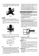
1. Installing bits
(1) Remove the motor housing from base as follows.
(a) Open the lever. (Fig. 1)
Fig. 1
(b) While holding the base, turn the motor housing
counterclockwise.
(c) Turn it until the pin in the base is disengaged from
the groove in the motor housing. Lift the motor
housing free from the base.
(2) Clean and insert shank of bit into the collet chunk until
shank bottoms, then back it out approximately 2 mm.
(3) With the bit inserted and 16 mm wrench holding the
armature shaft, use the 23 mm wrench to firmly
tighten the collet chuck in a clockwise direction
(viewed from under the router). (Fig. 2)
Fig. 2
(4) When using the 8 mm diameter shank bit, replace the
equipped collet chuck with the one for 8 mm diameter
shank bit which is provided as the standard accessory.
CAUTION:
Ensure that the collet chuck is firmly tightened after
inserting a bit. Failure to do so will result in damage
to the collet chuck.
2. Removing bits
When removing the bits, do so by following the steps
for installing bits in reverse order.
INSTALLING THE MOTOR HOUSING
WARNING:
Be sure to switch power OFF and disconnect the plug
from the receptacle to avoid serious trouble.
1. Installing the motor housing
(1) Open the lever.
(2) While holding the base, insert the motor housing into
the base aligning the pin with the groove in the base.
(3) Confirm that the pin and the groove are aligning.
Rotate the motor housing clockwise into the base.
(4) Close the lock lever.
Fig. 3
CAUTION:
You should be able to clamp the locking lever without
excessive force. Excessive force may damage the
base. You should not be able to move the motor in
the base when the lever is clamped. To adjust the
lever’s clamping force, open the locking lever and turn
the knob nut in small increments. Turning the knob
nut clockwise tightens the lever, while turning the
knob nut counterclockwise loosens the lever.
HOW TO USE THE ROUTER
WARNING:
Be sure to switch power OFF and disconnect the plug
from the receptacle to avoid serious trouble.
1. Adjusting depth of cut
(1) Place the tool on a flat wood surface.
(2) Open the lever and turn the motor housing until the
bit just touches the flat surface. (Fig. 4)
Fig. 4
Motor
housing
Base
Lever
23mm wrench
Bit
Collet
chuck
16mm
wrench
Loosen
Tighten
Motor
housing
Groove
Pin
Knob nut
Base
Lever
Motor
housing
Index line
Graduation
Scale ring
Base
Lever
Summary of Contents for M 12SC
Page 9: ...8 ...
Page 10: ...9 ...
Page 11: ...10 ...
Page 12: ...701 Code No C99133011 Printed in China Hitachi Koki Co Ltd ...


