background image

12

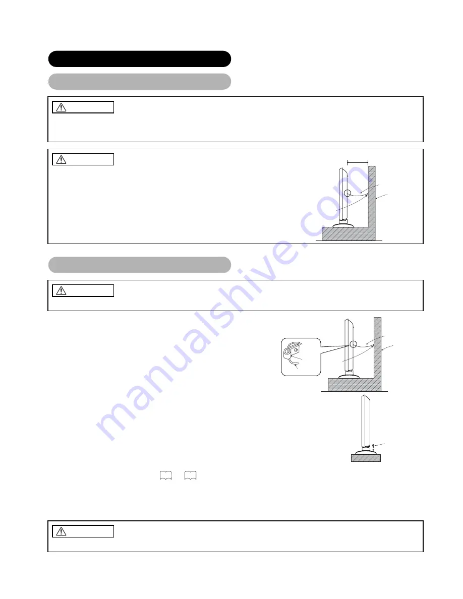
Securing to a wall or pillar

Using a commercially available cord, chain and clamp, secure the set to a firm wall 
or pillar.

Securing desktop

(1) Using wood screws (two), fasten the set to the clamping screw holes on the rear of the stand 

as shown.

(2) Using commercially available wood screws, secure the set firmly in position.

Read SAFETY INSTRUCTIONS ( 

 to 

 ) carefully to ensure maximum safety before proceeding to 

these steps:

• Choose an appropriate site and install the product on a level table where the stand is secure.

• Install the monitor to have ready access to a power socket available.

• Make sure that the power switch of this device is turned off.

Use one of the special mount units to install this product. A mount of insufficient strength or inadequate design can cause 
overturning or dropping and result in fire, electrical shock or injury. Please note that our company assumes absolutely no 
responsibility for personal injuries or property damage caused by use of other mount units or improper installation.

• In order to prevent an internal temperature increase, maintain a space of 10cm (4 inches : For a 

desktop setup) or more between the sides and other objects such as walls, etc., so that the 
ventilation holes are not blocked.(

*

)

INSTALLATION INSTRUCTIONS

Installation

WARNING

CAUTION

10cm or more*

Clamp

Cord or chain

Wall or Pillar

Have this unit mounted in a stable place. Take measures to prevent it from tumbling down to avoid possible physical injury.

Loosen a cord or chain enough while operating power swivel to avoid possible troubles.

Anti-tumble measures

CAUTION

Hook

Wall or Pillar

Clamp

Cord or chain

Cord or chain

Wood screw

Two places

3

6

CAUTION

Summary of Contents for LCD Monitor

Page 1: ...ture Notes on lnstallation Work This product is marketed assuming that it is installed by qualified personnel with enough skill and competence Always have an installation specialist or your dealer install and set up the product HITACHI cannot assume liabilities for damage caused by mistake in installation or mounting misuse modification or a natural disaster Note for Dealers After installation be ...

Page 2: ......

Page 3: ...cially because they would cause discoloration scratches or cracks Large screen high definition LCD panel The 32 inch color LCD panel with a resolution of 1366 H X 768 V pixels creates a high definition large screen aspect ratio 16 9 and low profile flat display Free from electromagnetic interferences from geomagnetic sources and ambient power lines the panel produces high quality display images fr...

Page 4: ...THER FEATURES 41 Automatic Store 41 Audio Switching 42 Power Save Mode 43 DVD Player STB Selection 43 Signal Check RGB mode 44 TROUBLESHOOTING 45 Symptoms That Seemingly Appear to be Failures 45 Actions to Correct Abnormal Displays 47 PRODUCT SPECIFICATIONS 48 Signal Input 49 Recommended Signal List 50 CONTENTS Note about This Manual The information in this manual is subject to change without noti...

Page 5: ...fy the monitor The monitor contains high voltage components Modification could result in fire or electrical shock Never remove any fixed cover Do not give the monitor any shock or impact If the monitor should be shocked and or broken it could result in an injury and continued use could result in fire or electrical shock If the glass panel is broken or damaged immediately turn off the power switch ...

Page 6: ...hem because this could result in the inadvertent placing of heavy objects on the concealed power cord or cables Do not pull the power cord and cables When connecting and disconnecting the power cord or cables do it with your hand holding the plug or connector Do not place the cord near the heater Do not touch the power plug just after disconnecting it from the power outlet to prevent electric shoc...

Page 7: ...tor in the following places Hot places such as near heater place exposed to the direct rays of the sun A place where the temperature is widely changing Places with soot dust or high humidity Poor air ventilation place Place near fire A wet place such as bathroom or shower room Place where you can trip over it Always vibrating or strongly vibrating places Distorted or unstable places Please avoid i...

Page 8: ...not to drop the remote control Do not place heavy objects on the remote control Avoid strong rays Any strong rays such as direct sun rays or room lighting onto the remote control sensors could invalidate the remote control Avoid radio interference Any interfering radiation could cause distorted images or noises Avoid radio generator such as a mobile telephone transceiver etc around the monitor Set...

Page 9: ...luminating fluorescent lamps inside the panel Because of this the temperature of the panel surface may rise in some cases Also LCD panels are made of finely processed glass so please avoid pushing by fingers or hands and giving strong impact on the panel It may cause damage to the LC cells and or there is danger of glass breakage About the power swivel Do not put hands or faces close to the monito...

Page 10: ...moving the main unit As this product is heavy whenever it is moved two people are required to transport it safely Whenever the unit is moved it should be gripped by holding the top of the monitor and the unit should then be held at the base on both sides for stability as shown Do not hold the speaker units while moving the set The speaker holders may be separated off and the monitor may fall and i...

Page 11: ...TI MODE button MULTI PICTURE button MUTE button Do not use new and old batteries together The batteries could explode or leak resulting in fires physical injury or stains When loading batteries observe their correct polarities as marked on the product If loaded in the wrong direction the batteries could explode or leak resulting in fires physical injury or stains Loading Batteries CAUTION ATTENTIO...

Page 12: ...Lit Indicates the mode that has been selected Press the button to change modes when the LED is lit Blinking Indicates that the maker of DVD or STB can be set You can set up the maker of DVD or STB while the LED is still blinking 30 sec For details refer to 43 43 44 ZOOM Press this button can change Picture size SWIVEL Press this button to rotate TV Use cursor key to select the degree of rotation R...

Page 13: ...rough a TELETEXT service subject to subtitle service broadcasting CANCEL This allows the screen to return to the TV mode temporarily while searching for a required text page When the required text page has been received the page number will be displayed at the top left of the screen Press the CANCEL button again to display the TELETEXT screen RED GREEN YELLOW BLUE Each of these buttons selects a l...

Page 14: ...t strength or inadequate design can cause overturning or dropping and result in fire electrical shock or injury Please note that our company assumes absolutely no responsibility for personal injuries or property damage caused by use of other mount units or improper installation In order to prevent an internal temperature increase maintain a space of 10cm 4 inches For a desktop setup or more betwee...

Page 15: ...l from AV3 and AV5 that is displayed on the screen at the time Secure connecting cables to the stand with the provided clamps HDIM HDMI High Definition Multimedia Interface is a digital interface based on DVI Digital Visual Interface which is an added function for audio visual equipment It does not have degradation by transmission since it is digital With only one cable it is possible to transmit ...

Page 16: ...d using a parallel flat feeder wire as interference may occur causing reception to be unstable and stripe noise to appear on the screen Avoid using indoor antenna as this may be affected by interference Please use CATV net or outdoor antenna Keep the power cord as far away from the antenna wire as possible For safety install an external antenna conforming to AS1417 1 applicable for Australia only ...

Page 17: ...optional conversion adapter or the adapter provided with the personal computer may be necessary in some cases For details refer to the instruction manual of the personal computer or ask the personal computer manufacturer or your local retail dealer INSTALLATION INSTRUCTIONS continued Connecting to a PC 48 52 AUDIO IN ANALOG INPUT RGB 2 DIGTAL INPUT RGB 1 Power cable connector Monitor rear panel Sp...

Page 18: ...TION How to connect the speaker cables Press down the lever Insert the wire Release the lever Treating the wire ends Please prepare the supplied speaker cables Pull off while twisting Red Black Connect the red black colored wire Connect the red colored wire Red Black Connect the red black colored wire Connect the red colored wire Ferrite core Ferrite core Twist the heads How to connect the speaker...

Page 19: ...d and the rear of it When the monitor is swiveled the connectors may drop out and generate heat It could cause fire and or connector failures Moreover when wiring up and securing these cables give suitable slack not to rub the stand during swiveling or not to block the action of swivel INSTALLATION INSTRUCTIONS continued Mounting the Side Input 13 Side input Screw X 1 Included with side input 2 Mo...

Page 20: ...wer cord plug to the power outlet The type of plug is different from this drawing for some countries Use only the power cord provided Do not use a power supply voltage other than that indicated AC100 240V 50 60Hz as this may cause fire or electric shock INSTALLATION INSTRUCTIONS continued Power Cord Connection 2 1 CAUTION ...

Page 21: ...ng Off Off When the main power switch is set to OFF Lights red Off standby When the main power switch is ON and the POWER button on the remote control or the SUB POWER button on the upside of the monitor is OFF Lights green On When the main power switch is ON and the POWER button on the remote control or the SUB POWER button on the upside of the monitor is ON Lights orange Off Power Save When the ...

Page 22: ...V6 AV5 Size Switching Panoramic Cinema Full Zoom 4 3 Full INPUT SELECT buttons ZOOM button RECALL button CHANNEL UP DOWN button PROGRAM SELECT buttons When you want to Set the display size to Input signal Display screen Remarks Play a 4 3 image in a 16 9 screen faithfully 4 3 4 3 signal Blanking occurs on both sides Play a 4 3 image in a 16 9 screen with the height and width of the middle of the s...

Page 23: ...r ATTENTION Using a wide screen monitor This monitor has a screen mode selection feature If an incompatible screen mode is selected to play certain software such as a TV program the image would appear different from the original Take this into consideration when making screen mode choices Use of this monitor in its enlarged display mode with the wide feature enabled in coffee shops hotels and othe...

Page 24: ...ide magenta will be displayed The volume setting can be lowered by pressing the button while the audio is mute The muting can be cancelled by pressing the button or MUTE button while the audio is mute The audio from the headphone terminal is not mute The audio from the speaker is automatically mute while connecting the headphone to the headphone terminal of the side input AV5 When the MUTE button ...

Page 25: ... It could cause a failure of the stand Do not put hands or faces close to the monitor while operating the swivel function It could cause a physical injury Use special caution in households where children are present Do not put any object like a vase near the monitor in swiveling area It would cause a breakage of the object and or a failure of the stand Place the monitor on the stable location or t...

Page 26: ...approximately 6 seconds OPERATING INSTRUCTIONS continued Input Signal Screen Display RGB Input mode Signal mode Input horizontal frequency Input vertical frequency Off timer On timer RECALL button AV1 Composite Min OFF ON VIDEO Input mode Signal mode Off timer On timer 1 ABCDE Min OFF ON TV TV position Name Off timer On timer Sound mode ...

Page 27: ... buttons to select picture The selected input display number would change green The TV channel can be changed by pressing the CHANNEL UP DOWN button on the remote control The audio can only be output from picture A in 4 pictures mode The component signal input mode cannot be selected in pictures B Refer to the table for 4 pictures mode Pressing the MULTI PICTURE button at the 4 pictures mode will ...

Page 28: ...n will cancel the 2 pictures display Frequency Mode in the Setup Menu should be set to Movie when sub screen is the component signal of 1080i 50 or 1080i 60 AV1 Displays the VIDEO input signal of the sub screen 2 Pictures Split 4 Pictures Activating the Split mode from the video input screen Activating the MULTI PICTURE mode from the RGB input screen NOTE Even if the input of the horizontal vertic...

Page 29: ...re and the other still The Strobe mode will display 12 pictures with the last picture active while other 11 windows are still Pressing the FREEZE button again changes the screen back to the normal picture This function is also available from video input mode besides TV mode Refer to the table for Freeze function as below Split Strobe TV O O PAL SECAM O O NTSC3 58 4 43 O O 576i O O 480i O O 576p O ...

Page 30: ...and ADJUST buttons to adjust example Contrast Press the RETURN button to return to the previous screen If there is no operation for a period of one minute the Adjustment Menu screen will be closed automatically OPERATING INSTRUCTIONS continued Example Selecting the Picture screen from TV Video mode Using the Menu Screen On screen display system MENU button RECALL button SELECT ADJUST button OK but...

Page 31: ...nguage Auto Off Off Select Set Return OK Setup Auto Tuning Manual Tuning Fine Tuning Sort Teletext Language Auto Off Off Select Set Return OK Setup Auto Tuning Manual Tuning Fine Tuning Sort Teletext Language Auto Off Off Select Set Return OK Setup Teletext Language West Europe East Europe Cyrillic Greek Turkish Select Return Exit Setup Auto Tuning Mode Position Search Select Set Return OK Setup A...

Page 32: ...ng positions by CHANNEL UP DOWN button This is automatically set to On for those non broadcasting channels NR If this is set to On it helps to reduce the noise interference visible on the screen especially in the weaker signal reception areas Antenna Att If this is set to On it helps to reduce the noise inter ference visible on the screen in case of strong airwave Fine Tuning Decreasing the freque...

Page 33: ...V2 video input terminal Normally set this to Auto The signal mode of the input signal will be automatically recognized If the input signal contains much noise or has a low level at Auto and the operation is found erratic set this to match the input signal RGB1 This should correspond to the signal mode of the signal from the equipment that is connected to RGB1 DVI terminal RGB2 1st step This should...

Page 34: ...ency shrinks the right side Increases the dot clock frequency expands the right side Adjust for maximum character clarity This function is only for RGB2 It s not available grayed out for RGB1 DVI PC Clock Phase Slows the dot clock phase shifts slightly to left Advances the dot clock phase shifts slightly to right Adjust for clear character visibility This function is only for RGB2 It s not availab...

Page 35: ...s should correspond to the signal mode of the signal from the equipment that is connected to RGB2 D sub terminal RGB2 2nd step This step should be set only when Component is selected on the 1st step This should correspond to the signal mode of the signal from the equipment that is connected to RGB2 D sub terminal Normally set this to Auto The signal mode of the input signal will be automatically r...

Page 36: ...debars to the black sidebars when watching normal mode screen size area It is always set to Off when the monitor powered On It is recommended to set to Off to reduce the residual image Video Power Save This is used to reduce power consumption for video input when there is no video signal Setting it On will lead the monitor to the standby mode when the AV input with no signal is selected Freeze Mod...

Page 37: ...35 ENGLISH OPERATING INSTRUCTIONS continued PICTURE MENU TV Video mode ...

Page 38: ... be restored by pressing the OK button YNR Performs picture signal noise reduction Turn up to reduce noise CNR Performs color signal noise reduction Turn up to reduce noise And it will be fixed as Off only when selecting DVI STB mode Film Mode On Automatically detects the movie film material and faithfully reproduces the original film image Off Set to OFF when switching between images does not app...

Page 39: ... Select the single color screen when that is required to adjust R G B level individually depending on the user s preference And set it back to RGB mode that indicates all color after adjusting Press the OK button every time the setting is changed Red Darkens red only Lightens red only This adjusts R G B level or tint to make the color appear natural for the user s preference These settings are ind...

Page 40: ...el Color Temperature Normally set to Normal Color Temp Adjust Turn On when you wish to change color temperature is required to adjust depending on the user s preference Amplitude Red Brighter scene is decreased in reddish color Brighter scene is increased in reddish color Adjust color temperature depending on the user s preterence These settings are independently stored in each of the 4 Color Temp...

Page 41: ...ures the spacious sound effects of a stadium Perfect Volume This will automatically adjust volume so each channel and input has the same average volume level Reset off the function waiting to reset The original factory settings for the items of this Menu page can be restored by pressing the OK button Headphone Volume Turns down the volume Turns up the volume This is to set the volume for headphone...

Page 42: ... power to standby status when the indicated time period has elapsed On Timer hours minutes This automatically sets the power from standby to ON when the indicated time period has elapsed The settable time is 00 00 11 59 Input the required time by and SELECT buttons on the remote control OPERATING INSTRUCTIONS continued TIMER MENU LANGUAGE MENU ...

Page 43: ...ing is registered Red Yellow Green Cyan Blue Color Decoding Red For every Color Temperature 1 setting is registered Green Color For every input function and every Picture Mode 1 setting is registered Tint Audio Mode 1 setting is registered Treble For every Audio Mode 1 setting is registered Bass Balance 1 setting is registered Dynamic Bass For every Audio Mode 1 setting is registered Matrix Surrou...

Page 44: ...al sound broadcast When a monaural program is received sound mode display will appear in green You can press the CH I II button to select the sound mode between monaural and forced mono sound is same Each time the button is pressed or force mono appear cyclically on the screen OTHER FEATURES continued NOTE If sound signal is not strong enough for quality reception press the CH I II button until ap...

Page 45: ...by pressing the following buttons on the remote control simultaneously DVD Selection SAT Selection OTHER FEATURES continued Power Save Mode RGB sync signal Horizontal Yes No Yes No Vertical Yes Yes No No PC signal Active normal display Blank no display Operation mode On Off Indicating lamp Lights green Lights orange Power consumption 158W 3W or less DVD Player STB Selection Makers of DVD Player Se...

Page 46: ... remote control Status Display Action When Frequency Display is set to ON the input signal is switched or when the RECALL button is pressed A guide is displayed for the input terminal and the horizontal and vertical sync frequency When the sync signal is no longer detected A guide displays No Sync Signal and Power Save for approx 5 sec When the condition continues where the sync signal cannot be d...

Page 47: ...e display image appears flowing slantwise Text displayed across the screen appears vertically streaked with the characters in vertical columns blurred Adjust the dot clock frequency and phase Adjust the dot clock frequency first the dot clock phase next RGB input Text displayed across the screen appears blurred A fine pattern flickers when displayed on the screen Adjust the dot clock phase for the...

Page 48: ...tor may heat up This is not a malfunction Text characters are displayed with varying thicknesses The thicknesses of characters and lines may vary if images with a vertical resolution greater than 768 lines are displayed however this is not a malfunction The screen becomes dark and the images cannnot be seen during VTR special playback fast forward rewind This sometimes occurs when a component outp...

Page 49: ... adjustment for symptom 2 below when the characters are blurred on the entire screen Symptom 2 Text displayed across the screen appears blurred in its entirety Figure 2 A fine pattern flickers when displayed on the screen Figure 3 Example Figure 2 Figure 3 Adjustment procedure 1 Press the MENU button The Main Menu will be displayed 2 Press the SELECT button and select Setup 3 Press the OK button T...

Page 50: ...H V separate TTL level 2KΩ H V composite TTL level 2KΩ Sync on green 0 3 Vp p 75Ω Recommended signal 44 modes Video input Input terminals AV1 composite video input terminal RCA AV1 Y PB PR video input terminal RCA AV1 L R audio input terminal RCA AV2 composite video input terminal RCA AV2 Y PB PR video input terminal RCA AV2 L R audio input terminal RCA AV3 composite video input terminal RCA AV3 S...

Page 51: ...r 9 TMDS Data0 19 Hot Plug Detect 10 TMDS Clock Pin Input signal Pin Input signal 1 T M D S Data2 14 5V Power 2 T M D S Data2 15 Ground for 5V 3 T M D S Data2 4 Shield 16 Hot Plug Detect 4 T M D S Data4 17 T M D S Data0 5 T M D S Data4 18 T M D S Data0 6 DDC Clock 19 T M D S Data0 5 Shield 7 DDC Data 20 T M D S Data5 8 No Connect 21 T M D S Data5 9 T M D S Data1 22 T M D S Clock Shield 10 T M D S ...

Page 52: ...esolution Vertical frequency Hz 1 NTSC4 43 NTSC3 58 525 59 94 15 73 2 PAL SECAM 625 50 00 15 63 No Signal mode Horizontal frequency kHz Dot clock frequency MHz Remarks Signal Name Resolution Vertical frequency Hz 1 576i 576 50 00 15 63 2 480i 480 59 94 15 73 3 576p 576 50 00 31 26 4 480p 480 59 94 31 47 5 1080i 50 1080 50 00 28 13 6 1080i 60 1080 60 00 33 75 7 720p 60 720 60 00 45 00 No Signal mod...

Page 53: ...X 480 72 81 37 86 31 50 O 5 640 X 480 75 00 37 50 31 50 O 6 640 X 480 85 01 43 27 36 00 O 7 800 X 600 56 25 35 16 36 00 O 8 800 X 600 60 32 37 88 40 00 O 9 800 X 600 72 19 48 08 50 00 O 10 800 X 600 75 00 46 88 49 50 O 11 800 X 600 85 06 53 67 56 25 O 12 1024 X 768 60 00 48 36 65 00 O 13 1024 X 768 70 07 56 48 75 00 O 14 1024 X 768 75 03 60 02 78 75 O 15 480p 720 X 480 59 94 31 47 27 00 O EIA 861B...

Page 54: ...1600 X 1200 75 00 93 75 202 50 22 1600 X 1200 85 00 106 25 229 50 23 Macintosh 640 X 480 66 67 35 00 30 24 24 832 X 624 74 55 49 72 57 28 25 1024 X 768 74 93 60 24 80 00 26 1152 X 870 75 06 68 68 100 00 27 W XGA 1280 X 768 59 833 47 986 81 00 28 1280 X 768 69 997 56 137 94 760 29 W XGA 1280 X 768 59 876 47 776 79 50 WXGA Mode 1280X768 30 1366 X 768 60 015 47 712 85 50 WXGA Mode 1366X768 The type o...

Reviews: