background image

HiSpeed Fast Ethernet Switch

Part No. US7070447-001, Rev 01

Troubleshooting Guide

Summary of Contents for HS140-010

Page 1: ...HiSpeed Fast Ethernet Switch Part No US7070447 001 Rev 01 Troubleshooting Guide ...

Page 2: ...dress telephone and fax number Type of equipment serial number and software version number A description of any commands entered and the resulting output Whether you were trying to connect to other equipment 0120013 10 1 1 22 4 01 001 2 51 1 6 7 88 8 3 9 3 2 2 ...

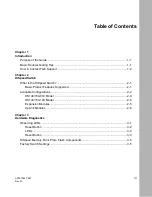
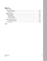
Page 3: ...iSpeed Switch What is the HiSpeed Switch 2 1 Basic Product Features Supported 2 1 Available Configurations 2 2 HS140 150 010 Model 2 4 HS140 150 100 Model 2 4 Expansion Modules 2 5 UpLink Modules 2 6 Chapter 3 Hardware Diagnostics Observing LEDs 3 1 Reset Button 3 2 LEDs 3 2 Reset Button 3 3 HiSpeed Memory Boot Prom Flash Components 3 5 Factory Switch Settings 3 5 ...

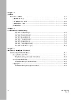
Page 4: ...Data Link Layer 5 2 Layer 3 Network Layer 5 3 Layer 4 Transport Layer 5 3 Layer 5 Session Layer 5 3 Layer 6 Presentation Layer 5 3 Layer 7 Applications Layer 5 3 Chapter 6 Methods of Managing the Switch CLI Command Line Interface 6 1 Using the Console Port 6 1 Troubleshooting a Console Connection 6 2 Using a Telnet Session 6 2 Troubleshooting a Telnet Session 6 3 Logging In 6 3 Troubleshooting the...

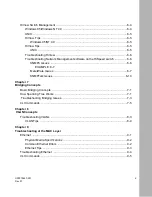
Page 5: ...SNMPC Issues 6 6 EXAMPLE 6 7 MeterWare Issues 6 7 SNMPTalk Issues 6 10 Chapter 7 Bridging Concepts Basic Bridging Concepts 7 1 How Spanning Tree Works 7 1 Troubleshooting Bridging Issues 7 3 CLI Commands 7 5 Chapter 8 VLAN Concepts Troubleshooting VLANs 8 3 VLAN Tips 8 4 Chapter 9 Troubleshooting at the MAC Layer Ethernet 9 1 Physical Media Specifications 9 2 Common Ethernet Errors 9 2 Ethernet Ti...

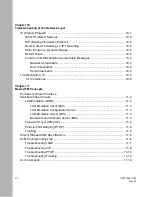
Page 6: ...ble 10 4 Troubleshooting IP 10 5 CLI Commands 10 6 Chapter 11 Basic ATM Concepts Permanent Virtual Circuits vs Switched Virtual Circuits 11 2 LAN Emulation LANE 11 2 LAN Emulation Client LEC 11 3 LAN Emulation Configuration Server 11 3 LAN Emulation Server LES 11 3 Broadcast and Unknown Server BUS 11 3 Classical IP over ATM CIP 11 4 Point to Point Bridging PTOP 11 4 Trunking 11 5 Hitachi HiSpeed A...

Page 7: ...Concepts HiSpeed FDDI Uplink 12 2 Cable Connections 12 3 Observing LEDs 12 4 FDDI Bridge Modes 12 4 Filtering Mode 12 5 Forwarding Mode 12 5 Promiscuous Mode 12 5 FDDI Troubleshooting Tips 12 5 Troubleshooting FDDI 12 6 CLI Commands 12 9 Index ...

Page 8: ...viii US7070447 001 Rev 01 ...

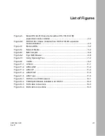
Page 9: ...igure 5 1 Network Media 5 2 Figure 6 1 MIB Compiler 6 8 Figure 6 2 Fig2 MIB Browser 6 9 Figure 7 1 Using Spanning Tree 7 2 Figure 8 1 VLANs 8 2 Figure 11 1 VPI VCI 11 1 Figure 11 2 ATM LANE 11 2 Figure 11 3 ATM CIP 11 4 Figure 11 4 ATM PTOP 11 5 Figure 11 5 ATM Trunk 11 5 Figure 12 1 HS150 on an FDDI network 12 1 Figure 12 2 FDDI Uplink Module installed in an HS150 12 2 Figure 12 3 SAS cable conne...

Page 10: ...viii US7070447 001 Rev 01 ...

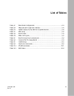
Page 11: ...link modules for the HS15 010 and HS150 100 2 6 Table 3 1 LED status 3 2 Table 3 2 RJ 45 LEDs 3 4 Table 3 3 LEDs on FX ports 3 4 Table 4 1 RJ 45 Connector pin assignments 4 2 Table 4 2 Console Port Pin Assignments 4 4 Table 8 1 VLAN Entries 8 4 Table 8 2 Useful CLI Commands 8 4 Table 10 1 IP address classes 10 1 Table 12 1 LED States 12 4 ...

Page 12: ...x US7070447 001 Rev 01 ...

Page 13: ...red to as divide and conquer By using this technique the problemis divided into smaller components making it easier to isolate and identify the problem To avoid overlooking the obvious when focusing on a specific problem ask yourself the following questions Has this functionality ever worked before When did this problem start happening What recent changes have been made to the network Software upg...

Page 14: ...hi s Internetworking Solution Center Hours Monday Friday 7 a m to 6 p m Pacific Standard Time PST Phone 1 800 611 4551 or 408 588 3119 Fax 408 988 9156 E mail hi assist hitachi com WWW http www internetworking hitachi com solution center To expedite the troubleshooting process please have the following information available when contacting Hitachi Technical Support Model and serial number of the s...

Page 15: ...tch is captured and the results are written to the file dispcfg dat Refer to dispcfg doc for instructions on how to run the batch program Forward the results to Hitachi s Technical Support Team via the WEB or email If using a browser type in the following URLs to download the files ftp ftp hicam hitachi com outgoing dispcfg ftp ftp hicam hitachi com dispcfg doc Please email any suggestions comment...

Page 16: ...HiSpeed Switch Troubleshooting Guide 1 4 US7070447 001 Rev 01 Draft Level Hitachi Confidential ...

Page 17: ...timized The HiSpeed switch offers the scalability and flexibility to accept a range of high speed interfaces for connecting to FDDI ATM and WAN backbones Basic Product Features Supported The HiSpeed switch includes the following hardware and software product features Virtual LAN VLAN support for 10BASE T Ethernet and 100BASE T Fast Ethernet VLANs including VLANs over ATM virtual connections Loop d...

Page 18: ...rroring to allow monitoring of the activities of one port from another port Provides flow control to autosense buffer limits on the transmit port Supports Group 1 2 3 and 9 RMON Supports Simple Network Management Protocol SNMP agent for Management Information Bases MIB II and a private enterprise MIB Provides a service port for console connection to locally or remotely configure and manage the swi...

Page 19: ... uplink options Table 2 1 Base model configurations Model 10 Mbps TX Ports 10 100 Mbps TX Ports 100 Mbps FX Ports Total Ports Uplink Upgrades To HS 150 010 16 12 4 0 16 Yes To 32 ports with HS150 010 16 E HS 150 010 32 24 8 0 32 Yes Max port configuration HS140 010 16 2FX 12 2 2 16 No Max configuration HS140 010 32 2FX 24 6 2 32 No Max port configuration HS 150 100 8 0 8 0 8 Yes To 16 ports with H...

Page 20: ... 100BASE TX ports expansion module and no uplink capability Key Console port Reset button Power LED Onboard module Expansion module Figure 2 1 Model HS140 010 base model with an HS 150 010 16Eexpansion module installed HS140 150 100 Model The 100 models ship with an eight port module configured in the captive slot This module can consist of either eight ports of 10 100BASE TX or eight ports of 100...

Page 21: ...ntly three expansion modules available to upgrade or reconfigure the capacity of the base models Table 2 2 lists the available expansion modules Table 2 2 HiSpeed switch expansion modules Module Number 10 Mbps TX Ports 10 100 Mbps TX Ports 100 Mbps FX Ports Base Model HS150 010 16 E 12 4 0 HS140 150 010 HS150 100 8 E 0 8 0 HS140 150 100 HS150 100 8 FXE 0 0 8 HS140 150 100 10 100 BASE T 1 2 3 4 10 ...

Page 22: ... panel The uplink provides high speed server access for FDDI and ATM Only the HS150 010 and 100 models accommodates the uplink Table 2 3 lists the available uplink modules Table 2 3 Uplink modules for the HS15 010 and HS150 100 Model Ports Type Base Model HS150 ATM UL 1 Fiber Optic ATM LANE uplink module HS150 FDDI UL DAS SAS Fiber Optic FDDI uplink module HS150 FR UL 1 X 25 Frame Relay X 25 uplin...

Page 23: ... ISD software which tests the system to determine any hardware failures The system diagnostic s focus is to help identify and verify major system features and components such as the processor memory I O devices system buses packet switch and uplink interfaces on the switch The ISD software isd and download instructions isd doc are available on the Hitachi anonymous FTP server 204 48 18 63 If you a...

Page 24: ...X LEDs Table 3 1 LED status LED LED Color Status Action Required System Status Indicator Flashing green Normal operation None LED should flash every second This indicates that the switch is functioning normally Solid green Switch encountered abnormal condition You probably cannot log in to the switch Reboot Flashing amber Switch encountered abnormal condition Reboot the switch Solid amber Switch e...

Page 25: ...l to reset the switch Unlit No power to switch Check to see if switch is on If so turn it off and reboot If LED remains unlit replace the switch Port LED Activity Collision green amber Flashing or solid green Normal operation when port receives or transmits traffic None Unlit No traffic None Flashing amber Collisions in half duplex mode TX only None Port LED Link Diag green Solid green Good cable ...

Page 26: ... Solid Flashing LED lights when data is being received or transmitted Off There is no data transmission currently on the link Collision Amber Flashing Collision when in half duplex mode Table 3 3 LEDs on FX ports LED Color State Description Activity Green Solid or Flashing Port is receiving or sending data Off No transmission on port Collision Amber Currently not supported on FX ports Link Green S...

Page 27: ...ytes compressed system code compressed systems diagnostics system configuration data system traces for debugging purposes Factory Switch Settings The HiSpeed switches are shipped from the factory without any IP configurations to the switch To perform any routing and network management to the switch you must assign an IP address to a VLAN on the switch Otherwise the switch will only provide core sw...

Page 28: ... Troubleshooting Guide 3 6 US7070447 001 Rev 01 Draft Level Hitachi Confidential Ethernet port settings autonegotiation is ON Spanning Tree is enabled These settings provide for switching in a single broadcast domain ...

Page 29: ...eiver of the other device The connection must be achieved through a crossover function which could be a crossover cable or a port that implements the crossover function internally All the 10 100BASE TX ports are wired for MDI X media dependent interface crossover Use the proper cabling to connect to devices as follows To connect to a switch hub or bridge use a crossover cable To connect to a works...

Page 30: ...ard RJ 45 connector are given in Table 4 1 The HiSpeed switches are shipped with the 10BASE T connectors configured as MDI X media dependent interface crossover These ports connect over straight cables to the network interface controller NIC card in a node or server similar to a conventional Ethernet repeater hub If you are connecting to another Ethernet hub or Ethernet switch you need a crossover...

Page 31: ...E to switch ports allow a file server to transmit frames to a switch while simultaneously receiving frames from the same switch This two way non CSMA CD full duplex communication allows an effective bandwidth of 200 Mbps between two devices Both the port speed and the duplex mode can be set using the CLI command ETHERNET CONFIG PORT For information on these commands refer to the HiSpeed Switch Use...

Page 32: ...tion and SNMP agent configuration and customize your network using the supplied menus and screens The pin assignments for the console port are provided in Table 4 2 The console port provides VT100 terminal emulation with the following parameter settings Baud Rate 9600 Data bits 8 Stop bit 1 Parity None Flow Control None Use the CLI commands CONSOLE SHOW CONSOLE CONFIG Table 4 2 Console Port Pin As...

Page 33: ...ev 01 4 5 Draft Level Hitachi Confidential to view and configure the console parameters For information on these commands refer to the HiSpeed Switch User Guide document number US7070424 001 that was shipped with your switch ...

Page 34: ...HiSpeed Switch Troubleshooting Guide 4 6 US7070447 001 Rev 01 Draft Level Hitachi Confidential ...

Page 35: ...the communications protocols used when transporting data from one network node to another The standard was initially written to provide both hardware and software vendors a common platform on which to develop products The model also serves as the basis for the IEEE LAN standards The OSI Model divides the task of computer communications into seven layers The model represents a hierarchical structur...

Page 36: ...niques are governed by the physical layer Examples of Physical Layer specifications are cabling 10BASE5 10BASE2 and 10BASE T 100BASE T etc type and size of the connector number of pins in the connector and the function of each of the pins Examples of Physical Layer devices are repeaters and hubs Layer 2 Data Link Layer This layer is responsible for assembling and disassembling data into frames The...

Page 37: ... Examples of Layer 3 devices are routers Layer 4 Transport Layer This layer ensures reliable delivery of data between networks All error checking acknowledgments retransmissions and data sequencing are handled by the Transport Layer Layer 5 Session Layer This layer provides for the ability for two processes on two different stations to form a connection for the purpose of communication with one an...

Page 38: ...HiSpeed Switch Troubleshooting GUide 5 4 Doc Part Number Version Number Draft Level Hitachi Confidential ...

Page 39: ...line interface CLI application for configuring the HiSpeed switch The CLI can be accessed from Console Port Telnet session Using the Console Port Connect a terminal to the HiSpeed switch using a null modem RS 232 serial cable A DOS Windows or Unix workstation running in terminal emulation mode can also be used The console port on the switch is configured as DCE which requires the use of a null mod...

Page 40: ...are 9600 8 1 none none 3 Check that your terminal or terminal emulator is correctly configured as VT100 4 Restart your terminal session 5 Check if there is a telnet session to the switch If so the following message appears telnetd This system IN USE via telnet You will then need to disconnect the telnet session 6 Reset the switch if it is necessary Using a Telnet Session The switch can be accessed...

Page 41: ...default the switch is configured to boot from flash After the switch has been booted the login prompt will be displayed Log in by entering admin in lowercase Login admin The switch will then prompt you for a password Enter switch in lowercase The password will not be displayed on the screen For security reasons change the admin password as soon as possible To do so use the SYSTEM CONFIG ADMINPW co...

Page 42: ...twork Management software is needed to probe the switch for statistics history alarms and events The following Network Management software have been tested with the HiSpeed switch SNMPC by Castle Rock MeterWare by Technically Elite further testing needed for Hitachi s private MIBs SNMPTalk by Epilouge However any Network Management software will run on the HiSpeed switch HiView can be installed to...

Page 43: ...k Device Dialog Box must be filled before launching the application When the HiView application has been launched for the first time the color on all Ethernet ports is black To distinguish between different VLANs you must assign different colors to the VLANs To upgrade the firmware on the switch using HiView a third party TFTP server process must be running HiView Tips UNIX HiView can only manage ...

Page 44: ... the HiSpeed switch SNMPC Issues For the RMON groups to work properly do the following 1 Create table entries with etherStatsStatus x historyControlStatus x alarmStatus x eventStatus x equal to createRequest 2 Fill out the table entries with relevant values 3 Set the xxxStatus field to valid In order to read the private MIBs via the SNMPC MIB browser modify the definitions in the NSGTC MIB 1 Open ...

Page 45: ... com DESCRIPTION This module defines the top level object identifiers for the HICAM Network System Group NSG These object identifiers are imported by other internally developed MIB modules enterprises hicam 399 nsg 2 nsgConventions 200 1 hicam OBJECT IDENTIFIER enterprises 399 nsg OBJECT IDENTIFIER hicam 2 MeterWare Issues For the RMON groups to work properly do the following Hitachi s vendor id m...

Page 46: ...ect the private MIBs to compile 4 From the Compiled MB Files list select the MIBs to be added to the Loaded MB Files list 5 After all MIBs have been added click on Reload Now Then click on OK Note The compiler will only compile one MIB at a time Verify that all the compiled MIBs appear in the window labelled Compiled MB Files Note After initially clicking on Reload Now an error message will appear...

Page 47: ...ential 6 Click on the menu bar labelled Tools and click on MIB Browser A dialog window will appear See Fig 2 below Go to this directory iso org dod internet mgmt and click on private enterprises hicam nsg Figure 6 2 Fig2 MIB Browser Note Viewing Hitachi s private MIBs requires further testing ...

Page 48: ...e 6 10 Doc Part Number Version Number Draft Level Hitachi Confidential SNMPTalk Issues For the RMON groups to work properly the mib rt file needs to be loaded in the same directory as SNMPTalk The mib rt file contains all MIB information ...

Page 49: ...destination address is in the Bridge Forwarding Table the packet will get forwarded onto the necessary port If the destination address in NOT in the Bridge Forwarding Table the packet will get flooded out all ports except the port on which the packet came in on This also applies to broadcast multicast and unknown unicast frames How Spanning Tree Works Bridging loops occur when there are redundant ...

Page 50: ... up of a combination of the MAC address and bridge priority If the root IDs are equal the bridge compares the costs least number of hops To ensure maximum performance the bridge will calculate the shortest path possible to get to the root bridge If both the root IDs and the costs are equal then the bridge compares the Transmitting Bridge ID s The bridge will keep the frame with the lowest Transmit...

Page 51: ...tes Listening Learning Blocking or Forwarding Troubleshooting Bridging Issues Problem PC is moved to a different port on the switch Users can no longer ping me Solution Wait for Spanning Tree to stabilize completely The default STA timer is 15 seconds for the ports to go from Listening to a Forwarding state To verify the port state type vvp You may also need to wait for the previous MAC entry to a...

Page 52: ...the amount of broadcast on my network Solution By design a bridge will forward all broadcast traffic However if the switch is specifically broadcasting Unknown Unicast packets verify that DLF is enabled The Destination Lookup Failure DLF mechanism slows down broadcasts sent from the CPU which may eventually consume total bandwidth on the network By default DLF is enabled To enable disable DLF on t...

Page 53: ...ilter all Displays all static entries in the Bridge Forwarding Table vbridge show bridge vlan Displays the bridge parameters per VLAN vbridge show port vlan Displays the Spanning Tree port parameters per VLAN vbridge config bridge vlan Modifies Spanning Tree parameters per VLAN vbridge config filter Add deletes static entries in the Bridge Forwarding Table ...

Page 54: ...HiSpeed Switch Troubleshooting Guide 7 6 US7070447 001 Rev 01 Draft Level Hitachi Confidential ...

Page 55: ...ed an IP address When routing is enabled a Virtual Router port is created and traffic is routed onto the VLAN via that Virtual Router port The HiSpeed switch implements VLANs on a per port s basis Ports assigned to a VLAN share the same broadcast whereas ports not belonging to that VLAN are not part of that broadcast domain By separating groups into different VLANs overall network performance is i...

Page 56: ...hed without the need to rewire the physical infrastructure Better security VLANs offer security by logically separating groups by departments functions etc therefore limiting and or restricting user access and priviledges to specific applications and resources Efficient use of network bandwidth VLANs maximize the efficient use of bandwidth on any given LAN segment since packets are forwarded only ...

Page 57: ...modify vlan VLAN CONFIG create vlan Verify that the user endstation s and the VLAN s on the switch are using the same subnet masks VLAN SHOW vrouter Verify that the gateway IP address es on the endstation s points to the IP address of the VLAN s it is connected to Check the ARP table on the switch to verify if the switch is learning the endstation s address es INET SHOW ARP Check the Routing table...

Page 58: ...N Entries Description CLI command VLAN entry created Virtual Port Information table VLAN SHOW vport Router Virtual Port id 33 Bridge Forwarding ARL table VBRIDGE SHOW fwt MAC entry with Port id 33 Routing table INET SHOW route Route entry with a directly connected VLAN Interface type Table 8 2 Useful CLI Commands VLAN SHOW vlan Displays the VLAN information VLAN SHOW vstats Displays all Virtual Po...

Page 59: ...this occurs all stations involved detect the collision and immediately stop transmitting After waiting a random time interval and ensuring that the line is free each station will retransmit If another collision occurs the station must wait another random time interval before attempting to retransmit After 16 tries the station reports that the network is unavailable and discards the frame Based on ...

Page 60: ...han one device is transmitting simultaneously Collisions are considered to be normal in an Ethernet environment CSMD CD is designed to detect and correct for this late collisions A collision detected after 64 bytes have been transmitted May indicate a malfunctioning NIC cable or a network segment that has exceeded the maximum length excessive collisions The maximum number 16 of consecutive collisi...

Page 61: ...umber of bits not divisible by eight and fails the checksum test This failure may be a result of collision a defective NIC bad cabling etc oversized frames Frame greater than the maximum Ethernet frame size of 1518 bytes This failure may be caused by jabbering or defective devices in the network Can cause FIFO buffer overflow collisions fragments CRC or alignment errors FCS errors Generated when t...

Page 62: ...corrective action Refer to Common Ethernet errors matrix for possible causes More than likely there is a physical layer problem caused by bad cabling malfunctioning NIC etc In most cases packets will be dropped by the switch due to excessive collisions late collisions FCS alignment errors oversized and undersized frames ETHERNET SHOW count port Transmit and receive queues can get full when the swi...

Page 63: ... basis ETHERNET SHOW count port Displays tx rx statistics Ethernet errors on a per port basis ETHERNET SHOW macaddrcount Displays the total count of MAC source address entries in the Bridge Forwarding Table ETHERNET CONFIG clear port Resets the port statistic counts to zero ETHERNET CONFIG port Configures the port speed duplexity autonegotiation ETHERNET CONFIG FLUSH portflush port tbd ETHERNET CO...

Page 64: ...HiSpeed Switch Troubleshooting GUide 9 6 Doc Part Number Version Number Draft Level Hitachi Confidential ...

Page 65: ...rotocol used by devices to communicate across a network IP utilizes a 32 bit address structure to identify the network and node number The three primary classes of IP addresses are as follows Table 10 1 IP address classes Class Range Subnet Mask Class A 0 127 255 0 0 0 Class B 128 191 255 255 0 0 Class C 192 223 255 255 255 0 Note 127 0 0 1 is reserved for loopback testing ...

Page 66: ... the network Examples of network applications using TCP are Telnet FTP SMTP UDP User Datagram Protocol Used by applications that do not require a reliable transport mechanism for communicating between devices across the network Examples of network applications using UDP are DNS TFTP SNMP RIP Routing Information Protocol The HiSpeed switch uses RIP version 1 to route IP packets across VLANs RIP a d...

Page 67: ...hile dynamic routes are learned Unlike dynamic routes static routes never age out To remove a static route it must be manually deleted from the routing table Default Route An address of 0 0 0 0 signifies a default route used for all unknown networks Typically the default route points to a router which maintains a complete routing table A default route is commonly used on a router as an entry point...

Page 68: ...ter in the path The ARP request to the destination host did not respond This may be a result of a user typing an incorrect IP address or a high number of physical layer errors on the destination network 1 Is the destination IP address correct 2 Is the destination host available 3 Are there any physical layer problems on the destination network 4 Is the default gateway correctly defined on the dest...

Page 69: ... Check the Routing table on the switch to verify that all networks are learned If not you may need to configure a default route of 0 0 0 0 INET SHOW route INET CONFIG ROUTE default Verify that the user endstation s and the VLAN s on the switch are using the same subnet masks VLAN SHOW vrouter Check all router interfaces to ensure they are up and active Verify that the HS150 port is in the correct ...

Page 70: ...ses the well known TCP port 23 for Telnet Verify that the socket is in a Listen state INET SHOW iconnect CLI Commands INET CONFIG ipr Enables disables Route Cache Forwarding INET ping hostname NumberofPackets Performs an ICMP echo request INET rlogin hostname Used when logging onto a Unix server INET CONFIG ROUTE ADD DEFAULT DELETE RMDEFAULT Commands available for configuring static and default ro...

Page 71: ...ch is an ATM edge device and provides Ethernet to ATM connections over an ATM network Within the physical link each Virtual Channel Connection VCC is uniquely identified by VPI VCI Virtual Path Identifier Virtual Channel Identifier pairs The VPI VCI identifiers allows the network to associate each cell with a virtual path and channel to switch data through Each VPI VCI pair has local significance ...

Page 72: ...ed Unlike PVCs SVC connections are not automatically re established after a network failure The HiSpeed switch implements the following ATM services LAN Emulation LANE Classical IP over ATM CIP Point to Point Bridging PTOP Trunking LAN Emulation LANE LANE emulates a traditional LAN ie Ethernet or Token Ring over ATM by mapping MAC addresses to ATM addresses connectionless technologies to connectio...

Page 73: ...Configuration Server The LAN Emulation Configuration Server LECS provides the LEC with the ATM address of the LAN Emulation Server LES to join an ELAN It also provides the LEC with configuration information The LEC can connect to the LECS in one of three ways Use ILMI Use the LECS well known address 47007900000000000000000000 00A03E000001 00 Use a Config Direct VCC of 0 17 one for each ELAN LAN Em...

Page 74: ... across ATM Because VLAN information is not propagated across ATM only one VLAN can communicate on a single virtual channel connection VCC PTOP can either use Permanent Virtual Connections PVCs or Switches Virtual Connections SVCs HiSpeed switch HiSpeed switch SVC or PVC R CIP IP 200 1 1 x CIP IP 210 1 1 x VLAN IP 192 1 1 x VLAN IP 197 1 1 x To route between different Logical IP subnets LIS over C...

Page 75: ...gh an ATM switch ensure the bi directional path is established per port interface on the ATM switch Valid PTOP index ranges from 0 through 15 When configuring PVC valid VCI values begin with 32 HiSpeed switch HiSpeed switch SVC or PVC VLAN 1 VCC 501 VLAN 2 VCC 502 VLAN 1 VCC 501 VLAN 2 VCC 502 PVC When configuring a SVC connection ensure the correct PTOP indees are mapped to the switch you are con...

Page 76: ...k module must be inserted into the lower PCI slot only A multimode fiber MMF cable is required for use with the 155 Mbps ATM uplink OC 3 module Bind LANE PTOP and Trunking services via the port service command portserv config create 34 Enable ILMI for LANE and signaling Employ an external router for communication between logically separate ELANs for CIP Every ELAN must have one unique LES BUS pair...

Page 77: ...G ENABLE lec lec id Ensure that you are using a valid LEC id Valid LEC values ranges from 0 through 31 ATM CONFIG CREATE lec lec id Ensure the ATM port is configured for SVC mode and ILMI is enabled By default the ATM port is set to PVC mode and ILMI disabled ATM CONFIG MODIFY port Problem The LEC connection is up and active but I cannot ping across the ATM network Solution Use the following solut...

Page 78: ...re that you are using the same UNI signaling version as that of the connected ATM switch ATM CONFIG MODIFY port If using SVC connections ensure that you are using the same UNI signaling version as that of the connected ATM switch ATM CONFIG MODIFY port If using SVC verify that the ATM address of the ARP Server is correct Also verify the ARP Server is up and active on the switch you are connecting ...

Page 79: ...outer Verify any of the CIP IP addresses must be on a different IP subnet than those VLANs existing on the HiSpeed switches ATM SHOW cip cip id VLAN SHOW vlan Verify the VLANs communicating with one another over ATM belong to different IP subnets VLANs belonging to the same IP subnet are not allowed to communicate with one another via CIP VLAN SHOW VLAN If using PVC verify the VCI values are ident...

Page 80: ...tions ensure that the ATM port is configured for SVC mode By default the ATM port is set to PVC mode ATM CONFIG MODIFY port If using SVC connections ensure that you are using the same UNI signaling version as that of the connected ATM switch ATM CONFIG MODIFY port If using SVC connections verify the following Port configured as SVC ILMI enabled and the UNI version is correct ATM CONFIG MODIFY port...

Page 81: ... and status is active for a specific VCC using VAC VCC number Problem The PTOP connection is up and active but I cannot ping across the ATM network Solution Use the following solutions Verify that all IP addresses subnet masks and gateways are set correctly on the VLANs and any attached devices Verify the ATM port service has been bounded to each VLAN PORTSERV CONFIG create 34 vps 34 Verify all AT...

Page 82: ...t the ATM port is configured for SVC mode By default the ATM port is set to PVC mode ATM CONFIG MODIFY port If using SVC connections ensure that you are using the same UNI signaling version as that of the connected ATM switch ATM CONFIG MODIFY port If using SVC connections verify the following Port configured as SVC ILMI enabled UNI version is correct ATM CONFIG MODIFY port Correct ATM address of ...

Page 83: ...annot ping across the ATM network Solution Use the following solutions Verify that all IP addresses subnet masks gateways are set correctly on the VLANs and any attached devices Verify the ATM port service has been bounded to all VLANs If not you will need to delete the Port service and re create it PORTSERV CONFIG remove phyport portserv PORTSERV CONFIG create 34 vps 34 Verify all ATM Trunk ports...

Page 84: ...lays all or a specified CIP status ATM SHOW ptop ptop ptop Displays all or a specified PTOP status ATM SHOW trunk trunk trunk Displays all or a specified Trunk status ATM SHOW ARP CIP LEC ATM CONFIG Commands available for creating deleting modifying and disabling enabling ATM services are CREATE DELETE MODIFY CIP LEC PTOP TRUNK DISABLE CIP PTOP TRUNK ATM STATS Commands available in displaying ATM ...

Page 85: ...vels on the primary ring while the secondary backup ring is utilized if the primary ring fails The data rate is 100 Mbps based on a timed token access method The total length of the ring can extend up to 200 kilometers with nodes spaced up to 2 kilometers over multimode fiber Figure 12 1 HS150 on an FDDI network Dual Ring DAS HS 150 SAS HS 150 Concentrator ...

Page 86: ...ding station where it is stripped off the ring and the token is released Station Management SMT unique to FDDI detects isolates and recovers network faults on the ring The HiSpeed switch participates in the ring recovery process as a function of SMT Built in timers are used by all stations to ensure timely transmission of data across the ring Beacon frames indicate that a logical problem has occur...

Page 87: ...s The FDDI Uplink provides two SC connector ports allowing for both a Single Attached Station SAS and Dual Attached Station DAS configuration Figure 12 3 SAS cable connections Figure 12 4 DAS cable connections Caution Must be running software version 1 4 4 or later M M M M M B A Dual Attached Concentrator To FDDI Network SAS Cabling SC Port A B Downstream FDDI DAS Device DAS HS 150 FDDI DAS Device...

Page 88: ...iscuous The configurations can be set using the following CLI command FDDI CONFIG BRIDGE MODE Table 12 1 LED States LED Status Board Status Description Yellow Green Off Off Fail Adapter is not functional or driver is not loaded Off On Ring Op Ring operation THRU B DAS wrap S for SAS On Off Cable Error Adapter not able to connect possible cable problem On On Ring Op Wrapped Ring operation wrap A or...

Page 89: ...d on the HiSpeed processor If the FDDI ring is very large and the number of directly attached Ethernet devices is limited FDDI forwarding should be employed Maximum number of entries in the FDDI Forwarding table is 256 Promiscuous Mode With FDDI Promiscuous mode all packets will be received and forwarded to the FDDI Uplink This configuration is not recommended as an increased load will be placed o...

Page 90: ...icast traffic to an Ethernet device directly attached to the HiSpeed switch Solution Use the following solutions Verify that physical port 34 is active using vvp If the bridge mode is set to Forwarding verify that the MAC address of the targeted Ethernet device has been learned in the FDDI Forwarding table This means that either the Ethernet device has to initiate the connection to the switch or r...

Page 91: ...ot ensure that RIP is active on all VLANs Problem The FDDI port does not wrap or unwrap go back into a ring under high traffic loads when the cable is removed attached Solution This is a known issue and currently there is no fix is available Resetting the switch will re initialize the switch back into the ring Problem FDDI performance is slower from FDDI through Ethernet than from Ethernet through...

Page 92: ... is currently an issue with the FDDI driver and buffer management Engineering is actively working to resolve the problem Please contact Hitachi s Internetworking Solution Center for further assistance Problem The switch appears to hang during the boot up sequence or never reaches the login prompt Solution Flash memory may have become corrupted Reformat and Zap flash memory ...

Page 93: ...s ring operational states FDDI SHOW PORT counters Reports the number of times the Link Confidence tests passed failed FDDI SHOW PORT status Displays the Connect state and PCM state of the switch FDDI SHOW PORT summary Summary of the SMT Port Configuration FDDI SHOW PORT counters Reports the number of times the Link Confidence tests passed failed FDDI SHOW SMT id Displays the SMT versions and stati...

Page 94: ...HiSpeed Switch Troubleshooting Guide 12 10 US7070447 001 Rev 01 Draft Level Hitachi Confidential ...

Page 95: ...US7070447 001 Rev 01 Index 1 Symbols Numbers A B 7 7 7 7 C 7 51 A A 4 5 4 5 5 8 D 71 Index ...

Page 96: ...Index 2 US7070447 001 Rev 01 4 4 E 5 4 4 4 F 1 4 G H 1 4 A 8 I B L 5 5 5 5 5 5 5 5 5 5 5 A 5 ...


Page 97: ...US7070447 001 Rev 01 Index 3 M 1A 8 2 1 8 2 1 N O B P 7 8 7 51 A 7 51 A 7 51 A 1 R C1 2 9 C1 2 5 S T ...

Page 98: ...Index 4 US7070447 001 Rev 01 5 5 U B 8 V 8 ...

Reviews: