


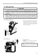


5
2.2 Main Component Units and their Functions
2. PARTS DESCRIPTION AND THEIR FUNCTIONS [Main Component Units and their Functions]
Air Dryer
This removes the mois-
ture in the compressed
air.
Cooling Fan Motor
Totally enclosed 4-pole
motor is used.
Cooling Fan
Squirrel cage fan is used
for cooling.
Oil Filter
This filtrates impurities
from lubricant.
Oil Separator
This separates lubricant
content from the com-
pressed air.
Minimum Pressure
/ Check Valve
This is found at the oil
separator's outlet and
regulate the minimum
pressure as 0.44 MPa or
over. By this action, the
valve prevent lubricant
from carryover due to in-
creased flow speed at low
pressure.
Air Intake Filter
This prevents foreign
bodies in the air from
being taken in the com-
pressor.
Relief Valve
This unlocks and re-
leases compressed air
when the inner pressure
of the separator abnor-
mally increases.
Oil Level Gauge
Oil Temperature
Control Valve
This retains the oil tem-
perature at the appropri-
ate level.
Suction Throttle Valve
This controls capacity of
air intake against load
fluctuation.
Driving Unit
This increases the revo-
lution of the main motor
with the help of a pulley
and a V-belt.
Air Discharge Duct
Oil cooler/Aftercooler
Assembly
Oil cooler and Aftercooler
are integrated into an as-
sembled unit, however,
the first cools lubricant
while the second cools
compressed air.
Main Motor
Totally enclosed, exter-
nal-fan cooled 4-pole
motor is used.
Starter
Oil Case
T h i s m a k e s p r i m a r y
separation of lubricant
content from the com-
pressed air, and its lower
part serves an oil sump.
Note: The figure shows the structure of 22 kW type.