background image

* ALTERNATIVE PARTS

--- 3 ---

ITEM

NO.

CODE NO.

DESCRIPTION

REMARKS

NO.

USED

PARTS

G  12S2

8 -- 01

44

980-778

SLIDE SWITCH (2P PILLAR TYPE)

1

45

984-750

TAPPING SCREW (W/FLANGE) D4X16

3

*

46

314-854

EARTH TERMINAL

1

FOR NOISE SUPPRESSOR

*

47

994-273

NOISE SUPPRESSOR

1

EXCEPT FOR SYR,USA,CAN

*

48

981-373

TUBE (D)

2

FOR NOISE SUPPRESSOR

49

953-327

CORD ARMOR D8.8

1

50

317-808

TAIL COVER

1

51

307-811

TAPPING SCREW (W/FLANGE) D4X16 (BLACK)

1

*

52

500-409Z

CORD

1

(CORD ARMOR D8.8)

*

52

500-237Z

CORD

1

(CORD ARMOR D8.8) FOR GBR

*

52

500-439Z

CORD

1

(CORD ARMOR D8.8) FOR AUS

*

52

500-447Z

CORD

1

(CORD ARMOR D8.8) FOR SYR,SUI

*

52

500-240Z

CORD

1

(CORD ARMOR D8.8) FOR USA,CAN

53

317-811

SWITCH HOLDER

1

54

937-631

CORD CLIP

1

55

981-373

TUBE (D)

2

FOR CORD

Summary of Contents for G 10SD2

Page 1: ...CAL DATA AND SERVICE MANUAL DISC GRINDERS G 10SD2 G 12S2 G 13SD SPECIFICATIONS AND PARTS ARE SUBJECT TO CHANGE FOR IMPROVEMENT LIST Nos G 10SD2 E234 G 12S2 E235 G 13SD E236 Sep 2001 G MODEL G 10SD2 G 12S2 G 13SD REVISED ...

Page 2: ...odel name s of our competitor s The symbol s utilized here is are as follows Symbols Utilized Competitors Company Name Model Name BOSCH GWS7 115 B G 12S2 Symbol Utilized Competitor Company Name Model Name MAKITA 9526NB C G 10SD1 Symbol Utilized Competitor Company Name Model Name MAKITA 9528NB C G 13SD MAKITA 9527NB C ...

Page 3: ...CAUTIONS IN SALES PROMOTION 9 7 1 Handling Instructions 9 7 2 Caution on Name Plate 9 7 3 Precautions on Usage 10 8 PRECAUTIONS IN DISASSEMBLY AND REASSEMBLY 11 8 1 Disassembly 11 8 2 Reassembly 12 8 3 Lubrication Points and Types of Lubricant 14 8 4 Tightening Torque 14 8 5 Wiring Diagrams 15 8 6 Insulation Tests 16 8 7 No Load Current Value 16 9 STANDARD REPAIR TIME UNIT SCHEDULES 17 Assembly Di...

Page 4: ...se Models are extensions of the HITACHI compact body disc grinder series and are intended to boost sales and draw attention to the whole line 3 APPLICATIONS Removal of casting fin and finishing of various types of steel bronze aluminum and various other metallic materials Grinding of welds or sections cut by means of a cutting torch Grinding of synthetic resins slate brick marble etc 4 SELLING POI...

Page 5: ...hanks an improved cooling mechanism and a high power motor Comparison of wear resistance of armature coils when dust and fine gravel are sucked into the machines Practical test data Comparison of torque when the stator coil temperature rise is 200 K Wear resistance of armature coil Both ends of the armature coil are sealed with heat resistant adhesive in addition to varnish treatment to minimize w...

Page 6: ...e commutator motor Type of motor Slide switch Type of switch Material Housing Tail cover Gear cover Packing gland Aluminum alloy die casting Painting Gear cover Packing gland Metallic silver Enclosure 1 6 kg 3 5 lbs Net 2 2 6 kg 5 7 lbs Gross Corrugated cardboard box Packaging Glassfiber reinforced polyamide resin green Depressed center wheel 100 mm 4 1 Side handle 1 Wrench 1 Standard accessories ...

Page 7: ...4 Weight 2 1 6 3 5 lbs Actual weight 1 65 3 6 lbs W W W min mm mm mm mm mm 62 dia 2 7 16 kg L G 10SD1 550 360 800 11 000 63 dia 2 1 2 207 8 9 64 261 10 1 4 60 2 3 8 67 2 5 8 1 6 3 5 lbs 1 6 3 5 lbs 62 dia 2 7 16 C 750 435 915 11 000 56 dia 2 7 32 195 7 43 64 257 10 1 8 70 2 3 4 81 3 3 16 1 5 3 3 lbs 1 5 3 3 lbs 65 dia 2 9 16 W L H Grip diameter Grip perimeter 1 Depends on market 2 Weight excludes ...

Page 8: ...12S1 63 dia 2 1 2 62 dia 2 7 16 C 56 dia 2 7 32 65 dia 2 9 16 W H Grip diameter Grip perimeter 207 8 9 64 261 10 1 4 60 2 3 8 67 2 5 8 1 6 3 5 lbs 1 6 3 5 lbs 206 8 1 8 286 11 9 32 73 2 7 8 76 3 1 55 3 4 lbs 1 55 3 4 lbs 195 7 43 64 257 10 1 8 70 2 3 4 81 3 3 16 1 5 3 3 lbs 1 5 3 3 lbs 115 4 1 2 550 360 800 11 000 115 4 1 2 750 455 887 11 000 115 4 1 2 750 435 915 11 000 B 59 dia 2 5 16 66 dia 2 1...

Page 9: ...9 7 8 H 63 2 1 2 W 72 2 53 64 Weight 2 1 6 3 5 lbs Actual weight 1 67 3 7 lbs W W W min mm mm mm mm mm 62 dia 2 7 16 kg L 56 dia 2 7 32 65 dia 2 9 16 W L H Grip diameter Grip perimeter C 125 5 750 435 915 11 000 195 7 43 64 257 10 1 8 70 2 3 4 81 3 3 16 1 5 3 3 lbs 1 5 3 3 lbs 1 Depends on market 2 Weight excludes cord side handle depressed center wheel wheel nut wheel washer and wheel guard ...

Page 10: ...D1 G 12S1 Stator coil temp rise Burn out point Stator coil temp rise K Fig 1 Comparison in torque vs rotation speed and stator coil temperature rise G 10SD2 and G 12S2 Fig 1 indicates 1 The Models G 10SD2 and G 12S2 are equipped with high power motors and improved cooling mechanisms and are superior to the Models G 10SD1 G 12S1 B and C in the rotation speed and the stator coil temperature rise at ...

Page 11: ... cooling mechanism As a result it is superior to C in both rotation speed and stator coil temperature rise at the same torque 2 The Model G 13SD has a tenacious motor with less rotation speed drop than C at the same torque This means that the working efficiency of the Model G 13SD is superior to C in heavy duty work 3 The stator coil temperature rise of the Model G 13SD is lower than that of C at ...

Page 12: ...ion against safety hazards the dangers inherent in the use of any electric power tool cannot be completely eliminated Accordingly general precautions and suggestions for the use of electric power tools and specific precautions and suggestions for the use of the disc grinders are listed in the Handling Instructions to enhance the safe and efficient use of the tool by the customer Salespersons must ...

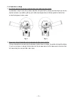
Page 13: ... side handle mounting position so that the operator s hand will not contact the depressed center wheel Fig 3 Fig 4 2 Never press the pushing button while the depressed center wheel is rotating If the pushing button is pressed while the depressed center wheel is rotating the spindle will stop immediately In such a case there is a danger that the wheel nut may be loosened so that the depressed cente...

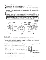
Page 14: ... sides and fix the hooks with the wing bolts 2 Place the J204 bearing puller on a supporting jig and push down on the armature shaft with a hand press to remove the Dust Seal 13 13 together with the Ball Bearing 14 14 Replace the Dust Seal 13 13 with new one because it is damaged by the removal of the Ball Bearing 14 14 3 Disassembly of the Stator Ass y 1 Remove the Armature 9 9 and then pull out ...

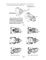
Page 15: ... 25 25 20 20 22 22 17 17 Push Push Gear puller J 128 Steel plate Step 4 Step 3 Step 2 Fig 5 8 2 Reassembly Push the parts together in the reverse order of disassembly with the precautions given below 1 Generously lubricate the teeth of Gear 17 17 and Pinion 6 6 with grease Rub grease onto the teeth with your fingers so that the grease reaches each tooth bottom Note that the Gear 17 17 and Pinion 6...

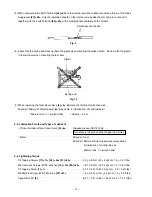
Page 16: ...rnal wire of the Noise Suppressor 47 48 and this wire to Tube D 48 49 with a solderless connection and connect it to the Slide Switch 44 45 If the Noise Suppressor 47 48 is not used connect this internal wire to the Slide Switch 44 45 after clamping Tube D 48 49 with the solderless connection Side A Side B Connect to the Brush Holder 40 41 Side A a Noise suppressor provided b Noise suppressor not ...

Page 17: ...f Hitachi power tool grease No 2 Unilube No 00 and tubine oil Mixture ratio 1 1 weight ratio Volume 0 5 cc 8 3 Lubrication Points and Types of Lubricant Pinion chamber of Gear Cover Ass y 4 4 Nippeko grease SEP 3A 5g Generously rub grease onto the gear and pinion Metal Mixed oil 0 5 cc Mixed oil Mixture of Hitachi power tool grease No 2 Unilube No 00 and turbine oil Mixture ratio 1 1 weight ratio ...

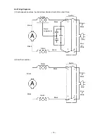
Page 18: ...alia New Zealand South Africa and China Stator Black Black Stator Black Black Noise suppressor Brown or Black Blue or White Cord 2 1 4 3 2 For other countries Stator Black Black Stator Black Black Brown or Black Blue or White Cord 2 1 4 3 A A Switch Switch ...

Page 19: ... M or more with DC 500V Megohm Tester Dielectric strength test AC 4 000 V 1 minute with no abnormalities 220 V 240 V products AC 2 500 V 1 minute with no abnormalities 110 V 127 V products 8 7 No Load Current Value After no load operation for 30 minutes the no load current value should be as follows Voltage V Current A max 220 230 240 1 7 1 7 1 6 110 3 2 115 3 0 ...

Page 20: ...ord Tail Cover Carbon Brush x 2 Housing Startor A Slide Bar Pinion Ball Bearing 628 VV Bearing Holder Armature Ball Bearing 608 VV Bearing Cover Ball Bearing 6201 DD Felt Packing Packing Gland Spindle Fringer General Assembly Pushing Button Gear Cover Ass y Lock Pin Gear Needle Bearing Wheel Guard Ass y G 12S2 G 13SD ...

Page 21: ... 18 Assembly Diagram for G 10SD2 ...

Page 22: ...REW W SP WASHER M4X10 2 19 316 490 BEARING COVER 1 20 620 1DD BALL BEARING 6201DDUCMAV2S 1 21 301 946 FELT PACKING 1 22 316 489 PACKING GLAND 1 23 307 127 SEAL LOCK SCREW W SP WASHER M4X12 4 24 302 047 WOODRUFF KEY 1 25 317 822 SPINDLE 1 26 301 945 FRINGER 1 27 308 386 MACHINE SCREW W SP WASHER M5X16 BLACK 2 28 301 949 SET PLATE 1 29 301 948 WHEEL GUARD ASS Y 1 INCLUD 27 28 30 310 787 WHEEL WASHER...

Page 23: ...307 811 TAPPING SCREW W FLANGE D4X16 BLACK 1 52 500 455Z CORD 1 CORD ARMOR D8 8 52 500 409Z CORD 1 CORD ARMOR D8 8 FOR INA 52 500 237Z CORD 1 CORD ARMOR D8 8 FOR HKG GBR 52 500 439Z CORD 1 CORD ARMOR D8 8 FOR NZL AUS 52 500 423Z CORD 1 CORD ARMOR D8 8 FOR SIN 53 317 811 SWITCH HOLDER 1 54 937 631 CORD CLIP 1 55 981 373 TUBE D 2 FOR CORD ALTERNATIVE PARTS 3 99 ...

Page 24: ...G DISCS 100MM C P20 10 PCS 1 606 314 053 SANDING DISCS 100MM C P24 10 PCS 1 607 314 054 SANDING DISCS 100MM C P30 10 PCS 1 608 314 055 SANDING DISCS 100MM C P36 10 PCS 1 609 314 056 SANDING DISCS 100MM C P40 10 PCS 1 610 314 057 SANDING DISCS 100MM C P50 10 PCS 1 611 314 058 SANDING DISCS 100MM C P60 10 PCS 1 612 314 059 SANDING DISCS 100MM C P80 10 PCS 1 613 314 060 SANDING DISCS 100MM C P100 10 ...

Page 25: ...IST LIST NO DISC GRINDER Model G 12S2 2001 8 22 E2 E235 501 502 1 2 3 4 5 6 7 15 33 8 9 10A 11 12 13 34 14 35 36 37 38 44 39 40 41 42 43 45 46 48 49 53 47 50 51 52 54 45 55 16 17 18 19 20 21 22 23 24 25 26 27 28 29 30 31 32 ...

Page 26: ...RING HK0709 1 17 317 821 GEAR 1 18 997 263 SEAL LOCK SCREW W SP WASHER M4X10 2 19 316 490 BEARING COVER 1 20 620 1DD BALL BEARING 6201DDCMPS2L 1 21 301 946 FELT PACKING 1 22 317 823 PACKING GLAND 1 23 307 127 SEAL LOCK SCREW W SP WASHER M4X12 4 24 302 047 WOODRUFF KEY 1 25 317 804 SPINDLE 1 25 319 655 SPINDLE 5 8 11UNC 1 FOR USA CAN 26 301 945 FRINGER 1 27 949 241 MACHINE SCREW M5X20 10 PCS 1 28 9...

Page 27: ... FOR SYR USA CAN 48 981 373 TUBE D 2 FOR NOISE SUPPRESSOR 49 953 327 CORD ARMOR D8 8 1 50 317 808 TAIL COVER 1 51 307 811 TAPPING SCREW W FLANGE D4X16 BLACK 1 52 500 409Z CORD 1 CORD ARMOR D8 8 52 500 237Z CORD 1 CORD ARMOR D8 8 FOR GBR 52 500 439Z CORD 1 CORD ARMOR D8 8 FOR AUS 52 500 447Z CORD 1 CORD ARMOR D8 8 FOR SYR SUI 52 500 240Z CORD 1 CORD ARMOR D8 8 FOR USA CAN 53 317 811 SWITCH HOLDER 1...

Page 28: ... 338 SUPER WASHER 1 EXCEPT FOR USA CAN 604 314 095 SANDING DISCS 115MM C P16 10 PCS 1 605 314 096 SANDING DISCS 115MM C P20 10 PCS 1 606 314 097 SANDING DISCS 115MM C P24 10 PCS 1 607 314 098 SANDING DISCS 115MM C P30 10 PCS 1 608 314 099 SANDING DISCS 115MM C P36 10 PCS 1 609 314 100 SANDING DISCS 115MM C P40 10 PCS 1 610 314 101 SANDING DISCS 115MM C P50 10 PCS 1 611 314 102 SANDING DISCS 115MM ...

Page 29: ...ST LIST NO DISC GRINDER Model G 13SD 2001 3 30 E2 E236 1 2 3 4 5 6 7 8 9 10 501 502 11 12 13 35 36 37 38 43 39 40 41 42 44 45 46 46 14 34 15 16 17 18 19 20 21 22 24 25 26 27 28 29 30 31 32 33 23 47 48 49 50 56 55 54 51 52 53 ...

Page 30: ...3 SEAL LOCK SCREW W SP WASHER M4X10 2 19 316 490 BEARING COVER 1 20 620 1DD BALL BEARING 6201DDCMPS2L 1 21 301 946 FELT PACKING 1 22 316 489 PACKING GLAND 1 23 307 127 SEAL LOCK SCREW W SP WASHER M4X12 4 24 302 047 WOODRUFF KEY 1 25 317 804 SPINDLE 1 26 301 945 FRINGER 1 27 949 241 MACHINE SCREW M5X20 10 PCS 2 28 949 454 SPRING WASHER M5 10 PCS 2 29 938 302Z SET PLATE A 1 30 994 321 WHEEL GUARD AS...

Page 31: ...27 CORD ARMOR D8 8 1 51 317 808 TAIL COVER 1 52 307 811 TAPPING SCREW W FLANGE D4X16 BLACK 1 53 500 409Z CORD 1 CORD ARMOR D8 8 53 500 237Z CORD 1 CORD ARMOR D8 8 FOR HKG GBR 53 500 439Z CORD 1 CORD ARMOR D8 8 FOR AUS 53 500 455Z CORD 1 CORD ARMOR D8 8 FOR CHN 53 500 447Z CORD 1 CORD ARMOR D8 8 FOR SUI 54 317 811 SWITCH HOLDER 1 55 937 631 CORD CLIP 1 56 981 373 TUBE D 2 FOR CORD ...

Page 32: ...TIONAL ACCESSORIES ITEM NO CODE NO DESCRIPTION REMARKS NO USED ITEM NO CODE NO DESCRIPTION REMARKS NO USED G 13SD Printed in Japan 010330N 3 01 501 938 332Z WRENCH 1 502 302 142 SIDE HANDLE 1 601 310 338 SUPER WASHER 1 602 994 309 HANDLE JOINT 1 ...

Page 33: ......

Reviews: