


10
ED-S3170
ED-X3270
11
ED-S3170
ED-X3270
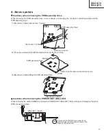
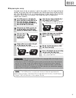
Adjustment procedure 2
(visual inspection)
1. First adjust [MIN] tone [G:].
2. Select [No.2] [G:].
If the background is [G] monochrome, press the
[MENU SELECT] key on the Remote control
transmitter to change to solid white.
3. View measurement point [No.2] and [No.3].
Lower the [G] color intensity only of the color point
whose [G] color is more intense than measurement
point [No.1].
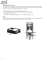
4. View measurement point [No.10] and [No.11].
Lower the [G] color intensity only of the color point
whose [G] color is more intense than measurement
point [No.1], and raise the intensity of the point
whose color intensity is lower than measurement
point [No.1].
5. Now adjust the [MIN] tone for colors [R] and [B].
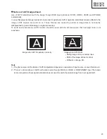
6. View measurement points [No.2], [No.3], [No.10]
and [No.11]. Adjust the [R] and [B] of each
measurement point so that they have the same
color as measurement point [No.1].
Adjustment technique:
First, adjust [B:] of the point whose color is to be
adjusted so that it approximates that of [No.1]. If
[R:] is low at this time, the image will have cyan
cast, in which case [R:] is increased. On the other
hand, if [R:] is excessive, the image will have a
magenta cast, in which case [R:] is decreased.
Overall, a cyan cast makes it easy to see color shading.
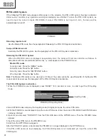
7. Next, view measurement points [No.4], [No.5],
[No.12], [No.13] and make similar adjustments.
8. Then adjust measurement points [No.6], [No.7], [No.8],
[No.9], [No.14], [No.15], [No.16] and [No.17].
This completes the [MIN] tone adjustments.
9. Make similar another three tones as described in
steps 1 to 8 above.
Summary of Contents for ED-S3170 series
Page 3: ...3 ED S3170 ED X3270 3 Names of each part Parts names ...
Page 4: ...4 ED S3170 ED X3270 Remote control transmitter ...
Page 12: ...12 ED S3170 ED X3270 5 Troubleshooting Check points at trouble shooting ...
Page 13: ...13 ED S3170 ED X3270 ...
Page 14: ...14 ED S3170 ED X3270 ...
Page 15: ...15 ED S3170 ED X3270 ...
Page 16: ...16 ED S3170 ED X3270 ...
Page 21: ...21 ED S3170 ED X3270 Replacing the Lamp ...
Page 25: ...25 ED S3170 ED X3270 Related Messages ...
Page 26: ...26 ED S3170 ED X3270 Regarding the Indicator Lamps Check the connector CNTH connecting ...
Page 30: ...30 ED S3170 ED X3270 7 Block diagram ...
Page 31: ...31 ED S3170 ED X3270 8 Connector connection diagram ...
Page 32: ...32 ED S3170 ED X3270 9 Wiring diagram ...
Page 33: ...33 ED S3170 ED X3270 ...
Page 34: ...34 ED S3170 ED X3270 ...
Page 35: ...35 ED S3170 ED X3270 ...
Page 36: ...36 ED S3170 ED X3270 ...
Page 37: ...37 ED S3170 ED X3270 ...
Page 41: ...A B C D E F G 5 4 3 2 1 6 6 5 4 3 2 1 PWB assembly DRIVE 1 C3S3 C3XM3 ED S3170 ED X3270 43 44 ...
Page 42: ...A B C D E F G 5 4 3 2 1 6 6 5 4 3 2 1 PWB assembly DRIVE 2 C3S3 C3XM3 ED X3270 ED S3170 45 46 ...
Page 43: ...A B C D E F G 5 4 3 2 1 6 6 5 4 3 2 1 PWB assembly DRIVE 3 C3S3 C3XM3 ED S3170 ED X3270 47 48 ...
Page 44: ...A B C D E F G 5 4 3 2 1 6 6 5 4 3 2 1 PWB assembly DRIVE 4 C3S3 C3XM3 ED S3170 ED X3270 49 50 ...
Page 45: ...A B C D E F G 5 4 3 2 1 6 6 5 4 3 2 1 PWB assembly DRIVE 5 C3S3 C3XM3 ED S3170 ED X3270 51 52 ...
Page 46: ...A B C D E F G 5 4 3 2 1 6 6 5 4 3 2 1 PWB assembly DRIVE 6 C3S3 C3XM3 ED S3170 ED X3270 53 54 ...
Page 47: ...A B C D E F G 5 4 3 2 1 6 6 5 4 3 2 1 PWB assembly DRIVE 7 C3S3 C3XM3 ED S3170 ED X3270 55 56 ...
Page 48: ...A B C D E F G 5 4 3 2 1 6 6 5 4 3 2 1 PWB assembly DRIVE 8 C3S3 C3XM3 ED X3270 ED S3170 57 58 ...
Page 49: ...A B C D E F G 5 4 3 2 1 6 6 5 4 3 2 1 PWB assembly DRIVE 9 C3S3 C3XM3 ED S3170 ED X3270 59 60 ...
Page 51: ...A B C D E F G 5 4 3 2 1 6 6 5 4 3 2 1 ED S3170 ED X3270 PWB assembly INPUT 1 C3S3 C3XM3 63 64 ...
Page 52: ...A B C D E F G 5 4 3 2 1 6 6 5 4 3 2 1 ED S3170 ED X3270 PWB assembly INPUT 2 C3S3 C3XM3 65 66 ...
Page 53: ...A B C D E F G 5 4 3 2 1 6 6 5 4 3 2 1 ED S3170 ED X3270 PWB assembly INPUT 3 C3S3 C3XM3 67 68 ...
Page 54: ...ED S3170 ED S3170 ED X3270 ED X3270 69 70 MEMO MEMO ...
Page 55: ...71 ED S3170 ED X3270 11 Disassembly diagram M Meter screw T Tapping screw ...
Page 56: ...72 ED S3170 ED X3270 M Meter screw T Tapping screw ...
Page 58: ...74 ED S3170 ED X3270 13 RS 232C communication ...
Page 59: ...75 ED S3170 ED X3270 ...
Page 60: ...76 ED S3170 ED X3270 Command data chart ...
Page 61: ...77 ED S3170 ED X3270 Command data chart ...
Page 62: ...78 ED S3170 ED X3270 Command data chart ...
Page 63: ...79 ED S3170 ED X3270 Command data chart ...
Page 64: ...ED S3170 YK No 0527E Digtal Media Division ED X3270 QR55441 Printed in Japan J ...


