background image


95 | 108


E-Compact MP-BB3 Series 

4.2. Internal Connections 

 
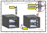
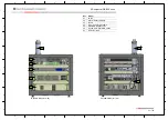
The following connections must be made:  
 

  RF cables 

  AC power cables and grounding 

  Control Modules cables 

  Rejection loads drawer cables 

  Ethernet Switch 

  Transport Stream cables (ASI) 


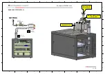
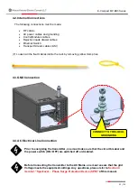
(7)  Loosen all the fixed cables inside the rack by removing yellow clamp ties: 


4.3. GND Connection 


4.4. AC Electrical Line Connection 


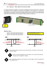
Prior to energizing the transmitter, one must make sure that the circuit breaker and 
the power switch (ON / OFF) are switched off or disabled. 


Before Connecting the transmitter to the AC Mains, one must ensure that the grid 
Voltage meets the equipment settings. Any questions, please refer to 

Section 4 

item 6.2. “Sparkover -  Phase Surge Protection Device (SPD)” 

of this manual. 


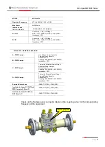
CONNECT TO THE LOCAL 

GROUNDING 

Summary of Contents for EC702MP-BB3

Page 1: ...8 E Compact MP BB3 Series Operation Manual UHF Digital TV Transmitters ATSC 3 0 420 Watts RMS ATSC 1 0 500 Watts RMS E Compact Medium Power Series Read before handling the equipment EC702MP BB3 EC704MP BB3 ...

Page 2: ...ts reserved Hitachi Kokusai Electric Comark LLC 104 Feeding Hills Rd Soutwhick MA 01077 United States of America Phone 800 345 9295 support comarktv com www comarktv com W A R N I N G All rights are reserved to Hitachi Kokusai Electric Comark LLC thus any reproduction adaptation translation or misuse of this Manual without prior written permission is prohibited except as permitted by copyright law...

Page 3: ...m Installation Requirements 13 1 Introduction 14 2 Minimum Requirements 14 2 1 AC Mains Wire Gauge 14 2 2 Grounding 15 2 3 Stability 15 2 4 Insulation 15 2 5 Atmospheric Discharge Protection System 18 2 5 1 Lightning rods 18 2 5 2 Protectors 18 2 6 Air Conditioning 18 2 6 1 Temperature 18 2 6 2 Humidity 19 2 6 3 Cooling 19 2 7 AC Load and Thermal Dissipation Information for Infrastructure Install ...

Page 4: ...ents 43 Main Menu Measurements Power 43 Main Menu Measurements Exciter Status 43 Main Menu Measurements HPA Drawers 44 Main Menu Measurements HPA Drawers RF Power 45 Main Menu Measurements HPA Drawers Software Version 45 Main Menu Measurements HPA Drawers Power Supply 45 Main Menu Measurements HPA Drawers Drain Current 46 Main Menu Measurements HPA Drawers Temperature 46 Main Menu Measurements Sof...

Page 5: ...V 40335 MOD GV 40336 PA 704MP MOD GV 40298 MOD GV 40309 71 4 6 1 Interfaces 72 4 6 2 Specifications 73 4 6 3 Power Amplifier Drawer Functional Description 74 4 6 4 Communication Interface COMM 75 4 6 5 Power Amplifier Signaling LED s 76 4 6 6 Power Supplies Signaling LED s 77 4 6 7 RPC 1600 48 1600 Watts Powers Supplies 77 4 6 8 Power Supply Redundancy Operation Power Reduction 78 4 3 EIA Low Pass...

Page 6: ...ection 95 Section 5 Initial Activation 97 1 Overview 97 2 Activation 98 3 Main Operations 100 3 1 Power Changing 100 3 2 Communication 100 4 Forbidden operations 100 5 Protections 101 5 1 Reflected Power 101 5 2 Over excitation 101 5 3 AC Mains Line Protection 101 5 4 Transmitter Operating Temperature Configuration 102 Section 7 Preventive Maintenance 103 1 Overview 103 2 Preventive Maintenance 10...

Page 7: ...dcasting Terrestrial LCD Liquid Crystal Display LPC Linear Pre correction MCCB Molded Case Circuit Breakers MER Modulation Error Rate MFN Multiple Frequency Network MSps Million Sample per Seconds N A Not Applicable NLPC Non Linear Pre Correction PA Power Amplifier PCMCIA Personal Computer Memory Card International Association PFC Power Factor Correction PID Packet Identifier PLL Phase Locked Loop...

Page 8: ...ilter EC704MP BB3 420 W UHF ATSC 3 0 Transmitter 6 poles filter 500 W UHF ATSC 1 0 Transmitter 6 poles filter Hitachi Kokusai Electric Comark LLC recommends that you carefully read this manual before installing or operating the equipment This manual is intended for use by qualified trained installers Read this manual before working with the product For personal and system safety as well as for opt...

Page 9: ...care with the equipment warranty criteria and technical assistance if needed Section 2 Minimum Installation Requirements This section comprises the minimum infrastructure requirements for installing these devices such as AC power protection against lightning and air conditioning Section 3 E Compact BB3 High Power Series UHF Digital TV Transmitter This section presents all equipment characteristics...

Page 10: ...ngs Never expose the equipment to rain moisture or direct sunlight in order to avoid the risk of fire or electric shock Avoid risks of accidents with regards heights and electricity Always install or maintain this equipment using qualified technicians Never turn on the equipment without connecting it to an Antenna or RF Load as this may cause serious damage to the Equipment Never unplug any Power ...

Page 11: ... in the installation site which is referred in the ANNEX 1 herein attached 3 3 Faults or defects caused by inadequate usage of the products not complying with the OPERATING MANUAL S or by lack of proper preventive maintenance recommended in the product s manual 3 4 In event of the goods and its accessories are submitted to 3rd Party maintenance unauthorized by the supplier as well as removal or vi...

Page 12: ...herefore in case of maintenance please contact Hitachi Kokusai Electric Comark LLC Phone 800 345 9295 Fax 413 998 1194 E mail support comarktv com While submitting a requestion for assistance please provide the following information Customer name Equipment Part Number Serial Number and a brief explanation of the occurrence With this intel we shall send the ARM number Authorization for Return of Ma...

Page 13: ...ature in compliance with the transmitter s standards 4 Surge suppressors W A R N I N G Minimum infrastructure requirements for installation and operation of TV transmitters Defects caused by improper installation or failure to comply with the minimum infrastructure requirements for installation and operation of the products will relieve Hitachi Comark of the contractual warranty ...

Page 14: ... in question if the cable length is longer consider a voltage drop in the cable maximum of 5 The section of the neutral conductor should be the same as the phase The section of the ground conductor must be the same as the conductor s phase AC load for infrastructure install A E Compact Series ATSC MODEL M110 M220 B220 T220 T380 A Wire Gauge A Wire Gauge A Wire Gauge A Typical Wire Gauge mm AWG mm ...

Page 15: ...xclusively used with the Comark TV transmitter and is sized to operate at least 30 above the kVA consumption specified by the TV transmitter For example for the TV transmitter with maximum consumption of 38kVA a voltage stabilizer or 50kVA UPS should be used Input voltage variations above 15 of the rated values specified for the Comark TV transmitter may cause damage to the equipment and in this c...

Page 16: ...cost of the final product This solution is much better than a conventional stabilizer due to double conversion The correction of the power factor PFC in the no break is necessary to reduce the cost of the electric energy as it reduces the reactive power VAr and the total power VA It is important to emphasize that it is not efficient to have a transmitter with power factor correction PFC powered by...

Page 17: ...Real Power W cos Φ Transmitter Power Factor Correction η nobreak Nobreak efficiency Double Conversion Online Nobreak Delta Conversion Online Nobreak STATIC BYPASS SWITCH CA CC CA CC RECTIFIER INVERTER BATTERY STATIC BYPASS SWITCH DELTA TRANSFORMER CONVETER DELTA PRINCIPAL INVERTER BATTERY ...

Page 18: ...d to the ground of the equipment rack It is favorable to use Faraday s Ring or Cage on hilltops and areas of many transmission sources which in turn isolates the transmitter from the electromagnetic fields avoiding interference caused by induction 2 6 Air Conditioning 2 6 1 Temperature For better performance and longer equipment life it is important that under the shelter the temperature is contro...

Page 19: ...IGH POWER TV TRANSMITTERS 0 to 80 There must never be condensation since water can damage the internal circuits of the transmitter 2 6 3 Cooling Cooling must be always in circulation with the air conditioning lowering the temperature of the room without external air intake For better performance of the cooling system the air conditioner must be installed in series with the transmitter cooling cycl...

Page 20: ... AC Load and Thermal Dissipation Information for Infrastructure Install E Compact High Power Broadband ATSC AC Load for infrastructure Install W Thermal Dissip for infrastructure Install BTU h EC702MP BB3 1092 2974 EC704MP BB3 1812 4478 ...

Page 21: ...cludes two models that provide transmitter power outputs TPO from 210 to 420 watts ATSC 3 0 Each power amplifier module has an excellent power density with 2RU and 19 and features features high gain Broadband Doherty LDMOS configured for transmitting up to 510 Wrms ATSC 3 0 Doherty Technology provides high efficiency and consumption cost reduction of up to 60 when compared to conventional transmit...

Page 22: ...Gain and Phase adjustments per drawer Isolated combiner enabling Hot Swap Main Control Software WEB Server and SNMP USB communication Drivers Passive elements Low pass filter before and after filter probes Optional Telemetry through GPRS interface Exciter GPS time base exciter s internal module RF Performance Modulation Standard ATSC 3 0 A 300 ATSC 1 0 A 53 Output Power Before Filter EC702MP BB3 E...

Page 23: ...56 W 1750 W Typical Thermal Dissipation ATSC 3 0 ATSC 1 0 EC702MP BB3 2309 BTU h 2524 BTU h EC704MP BB3 3874 BTU h 4263 BTU h Interfaces Monitor Control Interface Web GUI and SNMP Ethernet via RJ 45 Communication Interfaces Ethernet SNMP Format Ethernet IEEE 802 3u 10Base T 100Base TX Mechanical Features Equipment Weight Cabinet 19 10U mounting EC702MP BB3 64 Kg 141 0 lb EC704MP BB3 65 Kg 143 3 lb...

Page 24: ...s depending on the output power the redundancy option implemented and the number of channels at a given site 3 1 Single drive Dual drive optional and touch screen display optional Single Drive Ethernet Switch Control Module CM9001 Exciter not provided SINGLE DRIVE AC Power MCCB Ethernet Switch Ctrl I O Management RF Out Management CM9001 RF In Ctrl Ex FBF in RF sample Before mask filter RF Out Ctr...

Page 25: ...ment rack cabinet 10RU is supplied 01 Ethernet Switch Module 02 Main Control Module CM9001 03 Backup Control Module CM9001 optional 04 Main Exciter not provided 05 Backup Exciter not provided 06 EC702MP BB3 PA702MP MOD GV 40335 CH14 to CH 36 PA702MP MOD GV 40336 CH37 to CH 51 EC704MP BB3 PA704MP MOD GV 40298 CH14 to CH 36 PA704MP MOD GV 40309 CH37 to CH 51 07 MCCB AC Unit MOD 40323 08 Low Pass Fil...

Page 26: ...60C EC702MP BB3 FC6D80C EC702MP BB3 After Filter Sample Out A FWD Sample Out B FWD Sample Out C REF Sample Out D FWD AC Pow er RF Out Control I O FBA in FBF i n PA708HP Sample OUT FWD RF SAMPLE Sample OUT FWD PA PA704MP Power Amplifier RF In RF Out Control I O Comm PA AC Power line AC Mains RF Sampl e FBA in Exciter MCCB MOD 40323 _ 2kW EMC EMI filter Control Module Exciter block Comm RF Sample RF...

Page 27: ...EC704MP BB3 works with only 1 PSU but with an output power of 70 The Control Module CM9001 will show the REDUCTION POWER alarm EC704MP BB3 MAXIMUM PROGRAMMED POWER 350W ATSC 1 0 INPUT VOLTAGE NUMBER OF PSU OPERATING OUTPUT POWER 100 187 VAC 1 50 100 187 VAC 2 100 187 253 VAC 1 100 187 253 VAC 2 100 EC704MP BB3 MAXIMUM PROGRAMMED POWER 500W ATSC 1 0 INPUT VOLTAGE NUMBER OF PSU OPERATING OUTPUT POWE...

Page 28: ... Module CM9001 Power Amplifier PA704MP MCCB Module EC702MP BB3 MOD GV 40288 MOD GV 40335 40336 MOD 40323 EC704MP BB3 MOD GV 40288 MOD GV 40298 40309 MOD 40323 Passives Devices RF Low Pass Filter RF Out 50 Ω RF Output Sample Mask Filter Recommended EC702MP BB3 MOD 40243 EIA 1 5 8 MOD 40215 FC6D60C EC704MP BB3 MOD 40243 EIA 1 5 8 MOD 40215 FC6D80C N A NOT APPLY ...

Page 29: ...oring A user friendly interface on the transmitter controller chassis includes A front panel LCD screen that provides transmitter status information A front panel control interface for menu driven commands up down right left navigation escape and OK LED status indicators The CM9001 transmitter controller is paired with the TV exciter For transmitter systems configured optionally with dual drive th...

Page 30: ...ower On Signals power on equipment 04 Up key Display navigation keyboard 05 Down key 06 Left key 07 Right key 08 Enter OK key OK 09 Esc key Esc 10 FAULT On Indicates the presence of an Alarm Alarm in progress Pressing shows the list of active alarms on the display 11 PAST ALARM On Indicates that an alarm has occurred Pressing the display shows the alarm log list Front Panel 01 02 03 04 09 ESC OK 0...

Page 31: ...10 pin terminal block Expansion to Input output management and control connector 05 MANAGEMENT RJ45 Interface WEB access 06 EXCITER CONTROL DB9 male Exciter monitoring and control interface 07 TERMINAL USB 2 0 Type B Jack Access to devices Measurements 08 CONTROL I O 10 pin terminal block Input output management and control connector 09 FAN 2 pin terminal block Fan 24VDC power connector 10 COOLER ...

Page 32: ...l purpose input 0 A6 Analog general purpose input 1 A7 Digital general purpose input 0 A8 Digital general purpose input 1 A9 Digital general purpose input 2 A10 Digital general purpose input 3 B1 Relay 0 NO B2 Relay 0 COM B3 Relay 0 NC B4 Relay 1 NO B5 Relay 1 COM B6 Relay 1 NC B7 Digital general purpose output 0 B8 Digital general purpose output 1 B9 Digital general purpose output 2 B10 Digital g...

Page 33: ...of Exciter A B3 Double Exciter Output Status B4 External AC Phase Alarm B5 External RF Load Alarm B6 General Analog Output B7 External Modulator Exciter Alarm Status B8 General Digital Input B9 External Double Exciter Input Status B10 Relay Output Command CONTROL I O B1 B10 Control I O connector Rear panel A1 A10 A1 A2 A3 A4 A5 A6 A7 A8 A9 A10 B1 B2 B3 B4 B5 B6 B7 B8 B9 B10 EXCITER CONTROL DB9 mal...

Page 34: ...34 108 E Compact MP BB3 Series H G F E D C B A 8 7 6 5 4 3 2 1 H G F E D C B A 8 7 6 5 4 3 2 1 ...

Page 35: ...composed of a Graphic LCD Display two alarm management keys Fault AND Past Alarm two indication LED s Power On and Stream Loss and six Navigation keys This set allows equipment operation Through the display it is possible to visualize and change all of the parameters of the equipment The navigation consists of positioning the functions in the display according to the where the OK key triggers the ...

Page 36: ...e A active B Standby A standby B active 08 Forward power after filter value Watts 09 Reflected power value Watts DESCRIPTION 01 Some Functions Menus for security ask for your confirmation for access Use the keys to toggle between yes or no and the OK key to select the option DESCRIPTION 01 FWD after filter power graph bar 02 FWD after filter power value 03 Reflected power graph bar 04 Reflected po...

Page 37: ...ures The protection method consists of avoiding going off air which means reducing transmittion power to guarantee the equipment s integrity reducing the transmission power to guarantee the integrity of the equipment The reflectometer is a protective device for the equipment It is not recommended that it be used as a measuring instrument for the radiating system For this purpose a wattmeter or oth...

Page 38: ...phases and between the phase and the ground thereby absorbing the mains voltage peaks and not allowing them to damage the source 4 6 6 ALARMS Front Panel Signaling and Shortcut Keys FAULT When a fault occurs the equipment automatically takes protective actions turn off or reduce power and trigger the visual alarm on the front panel FAULT key lit in red When pressing the FAULT key the list of alarm...

Page 39: ...ms Equipment Remote Access Access to configure the equipment to operate on ethernet network Main Menu Setup The SETUP menu allows access and alteration of the equipment s parameter settings The transmitter is delivered to the customer configured with the parameters that were provided in the purchase act therefore it is not necessary to change the settings of equipment Setup Measurements System Ala...

Page 40: ...DESCRIPTION RF Mute on off Mute RF power on Enable RF power off Program Output Power Power W Changes the output power of the Equipment The maximum power changed in this parameter is defined in Equipment Setup Transmitter Operational Power Output Power Power Status W Demonstrates the direct output power of the equipment MENU PARAMETER DESCRIPTION Level Control on off Enable on Disable off the Autom...

Page 41: ...failure occurs Main Menu Setup Transistor Bias Adjustment Setting a transistors DC operating voltage or current conditions to the correct level so that any RF input signal can be amplified correctly by the transistor MENU PARAMETER DESCRIPTION Password XXXXX Stores the numeric value of the password Password ON OFF On off Enable or Disable the access password MENU PARAMETER DESCRIPTION Reflected Po...

Page 42: ...METER DESCRIPTION LDMOS Drain Voltage Voltage V LDMOS Drain Voltage The values are pre set at the factory Carrier Amp Current Current A Carrier Amp Current The values are pre set at the factory Peak Amp Gate Voltage Voltage V Peak Amp Gate Voltage The values are pre set at the factory Status HPA1 Ok Failure absence Power Amplifier 1 Status MENU PARAMETER DESCRIPTION PA Temperature Control 40 0 to ...

Page 43: ...ng others Main Menu Measurements Exciter Status Shows the Exciter status Ok Fail MENU PARAMETER DESCRIPTION Program Power Power W Programmed operating power on the equipment Output Power Power W Transmitter forward output power Reflected Power W Transmitter reflected output power ALC Reference Voltage Voltage V Voltage that controls the VGA Variable Gain Amplifier and output power Power Exciter St...

Page 44: ...pplies and Power Amplifiers PA in the menu Use the or keys to toggle between menus Power Supply 1 Power Supply 2 RF Power Software Version Power Supply Drain Current Temperature HPA Drawers POWER AMPLIFIER DRAWER EC704MP BB3 Top View PA IDENTIFICATIONS PA4 PA1 PA2 PA3 DRIVER POWER AMPLIFIER DRAWER EC702MP BB3 Top View PA IDENTIFICATIONS PA2 PA1 DRIVER ...

Page 45: ...ard Power Power W HPA forward output power Reflected Power Power W HPA reflected output power Driver RF In Power dBm RF signal input power of HPA Driver Driver RF OUT Power dBm RF signal output power of HPA Driver MENU PARAMETER DESCRIPTION Software Version PAM40000v0 00 PA1 Software PAM30000v0 00 PA2 Software PAM30000v0 00 PA3 Software PAM30000v0 00 PA4 Software PAM30000v0 00 Driver Software PAM3...

Page 46: ...wer supply voltage Driver MENU PARAMETER DESCRIPTION PA1 Current Current A Drain current PA2 Current Current A PA3 Current Current A PA4 Current Current A Driver Current Current A MENU PARAMETER DESCRIPTION Temperature Air In C F Ambient inlet air temperature at HPA PA1 Temperature C F PAs temperature PA2 Temperature C F PA3 Temperature C F PA4 Temperature C F Driver Temperature C F Driver tempera...

Page 47: ...tatus Shows the HPA communication status ok fail Main Menu Measurements CM Driver Temp Shows the temperature of Control module internal driver MENU PARAMETER DESCRIPTION Communication HPA1 Ok Fail Status of each HPA present in the equipment MENU PARAMETER DESCRIPTION Software Control Software Control version Software DIGI Software DIGI version ...

Page 48: ...alarms with their respective start end date and time Drawers Alarms It shows all alarms active or occurred in the HPA s Current Alarms Past Alarms Clear Alarm Log Reset alarm log list Main Menu System Alarms Log Current Alarms Shows the list of alarms currently occurring This function can also be accessed through the FAULT key located on the front panel ESC OK Use the or keys to toggle between ala...

Page 49: ...located on the front panel The Log Menu has the following structure See page 49 for the alarms list and their respective meanings ESC OK REF DESC 01 Amount of existing Logs 02 Log number pointed in order of occurrence 03 Indicates that the log refers to the start of the alarm 04 Indicates that the log refers to the end of the alarm 05 Indicates that the date that alarm was occurred 06 Indicates th...

Page 50: ...drawer alarms currently occurring Alarms Log Shows a detailed list with all drawers alarms with their respective start end date and time Clear Alarm Log Resets drawer alarm log list Main Menu System Alarms Log Drawers Alarms Current Alarms Shows the list of drawer alarms currently occurring See page 49 for the alarms list and their respective meanings Use the or keys to toggle between alarms List ...

Page 51: ...ist and their respective meanings In the absence of alarms the display shows the following message REF DESC 01 Amount of existing Logs 02 Log number pointed in order of occurrence 03 Indicates that the log refers to the start of the alarm 04 Indicates that the log refers to the end of the alarm 05 Indicates that the date that alarm was occurred 06 Indicates that the time that alarm was occurred 07...

Page 52: ... lower than threshold 100 VAC Notification PSU Critical Low AC Voltage PSU AC Voltage is lower than threshold 90 VAC Shutdown PSU High Current PSU Current is greater than threshold 31A PA702MP 32A PA704MP Notification PSU Critical PSU High Current PSU Current is greater than threshold 33 A Shutdown PSU High Temperature PSU temperature is greater than Threshold 65 ºC 149 F Notification PSU Critical...

Page 53: ...s 1000RPM in relation to software programmed value 1000 RPM Notification Fan Failure Fan rotation reaches 2000RPM in relation to software programmed value 2000 RPM Notification MAIN ALARM ALARM DESCRIPTION High Power Amplifier Communication Control Module cannot communicate with Power Amplifiers High Power Amplifier Active Alarm Current alarm on one or more Power Amplifiers Exciter Fail Control Mo...

Page 54: ...ents alarms check and all possible functional selections can be accessed remotely by a PC Browser or any Smartphone Browser by connecting to the embedded WEB page server inside of the equipment MENU PARAMETER DESCRIPTION IP Address 000 000 000 000 IP address of Ethernet Control Port v4 32 bit Subnetwork Mask 000 000 000 000 Ethernet Control Port Sub Network Mask Gateway 000 000 000 000 Ethernet Co...

Page 55: ...d page that allows you to navigate its parameters in an easy way and also make it possible to change its settings in a more friendly graphical environment This interface enables remote interaction between the user and the transmitter To access the interface it is necessary that the transmitter is connected to a local network through a cable CAT5 UTP with RJ45 connectors conforming to EIA TIA 568 B...

Page 56: ...rt located on its rear panel The equipment s IP address is fixed and is configured by accessing the keyboard display interface via Menu Equipment Remote Access Management Once the configuration is set open a browser and enter the IP address When intially loggin in use the factory password Login user Password linear For security reasons we recommend that once the first login is made change the fact...

Page 57: ...ipment name Channel transmittion 04 Forward Power Direct Power Monitor in real time 05 Reflected Power Reflected Power Monitor in real time 06 On Off Power 07 Section user 08 Exits the WEB Interface 09 Vertical Bar Menu 10 RED Qty of Current Alarms present ORANGE Qty of past alarms 11 Setup Sub Men 12 Measurements Sub Menu 13 Drawers Sub Menu 14 Remote Sub Menu 01 03 04 09 420 05 06 07 08 10 11 12...

Page 58: ...f alarms the number of active alarms Current Alarms will appear in the sidebar in red Log Alarms Shows the list of alarms currently occurring In the event of alarms the number of active alarms Current Alarms will appear in the sidebar in red List of alarms occurring Alarm help 04 05 06 02 01 03 07 ...

Page 59: ...arm Current Past alarm 02 Alarm Description 03 Date time alarm 04 Clear the entire list Upon confirming this action it will no longer be possible to recover the deleted list 05 Download the alarm list to the file named LogAlarms csv in the Download folder on your computer 06 Alarm help 07 Indication of the current page and command to switch between the previous or subsequent pages 420 420 ...

Page 60: ...arameters such as turning the ALC ON or OFF and setting the transmitter name PA Temperature Control Allows to set the operating temperature of the power amplifiers and set the temperature unit C F Time and Date Setup Sets the internal real time clock RTC of the equipment ...

Page 61: ...arm threshold Exciter Opens the external exciter control and management web Enter the external exciter IP adress and press connect Import Export Import Export Control Module settings Press Download to save the file export xx_xx_xx xx_xx_xx json in the PC downloads folder ...

Page 62: ...62 108 E Compact MP BB3 Series Upload a file settings Press Upload Select the json file Select the features to import and press save Press OK when the process is done ...

Page 63: ...ws the user to access the equipment s operating parameters read only Software Version Shows the Control Module s software version Power Shows the reading of the equipment s power parameters such as forward power and reflected power among others 4400 4400 2 08 50 420 420 6 ...

Page 64: ...s Shows the HPA s communication status Transistor Bias Shows the transistor DC s operating voltage or current conditions so that any RF input signal can be amplified correctly by the transistor Exciter Status Shows the Exciter s communication status 1 ...

Page 65: ... MP BB3 Series Drawers View the main status of all Power Amplifiers Drawers HPA Drawer Identification Individual status of each Drawer HPA Power Supply Shows the HPA Power Supply s status Power Supply 1 Power Supply 2 ...

Page 66: ...er Amplifier Shows the HPA Power Amplifier s status POWER AMPLIFIER DRAWER Top View PA IDENTIFICATIONS DRIVER POWER AMPLIFIER DRAWER EC704MP BB3 Top View PA IDENTIFICATIONS PA4 PA1 PA2 PA3 DRIVER POWER AMPLIFIER DRAWER EC702MP BB3 Top View PA IDENTIFICATIONS PA2 PA1 DRIVER ...

Page 67: ...67 108 E Compact MP BB3 Series Current Temperature VGS Peak Select the status to show 5 89 6 54 6 05 5 99 48 90 48 81 51 90 50 72 0 33 0 33 0 33 0 33 ...

Page 68: ...68 108 E Compact MP BB3 Series VGS Carrier Software Version 1 75 1 70 1 71 1 78 ...

Page 69: ...nd Ethernet network parameters to have remote access via a network connection SNMP Configures SNMP and download MIB table NETWORK Configures the Ethernet connection SNMP Status Download the MIB table file CMLinearMIB zip in PC download folder SNMP Traps config ...

Page 70: ...70 108 E Compact MP BB3 Series User Change the password Software Update Update Sofware Control Modle via bin file ...

Page 71: ...anel Removable power supply at the front panel of the drawer 2U Power Drawer for 19 rack Broadband power amplifiers Power transistors LDMOS Ampleon BLF 888E Automatic control of the quiescent currents of the power transistors depending on the temperature Automatic fan speed control according to power transistor s temperature Protection against VSWR and Overdrive Power Factor Corrector PFC at power...

Page 72: ...2 01 Signaling LED s 02 USB Interface 03 Removable front panel 04 Fan Air Filter 05 Removable Power Supplies front panel 06 Power Source 1 PS1 07 Power Source 2 PS2 08 LED status PS1 09 LED status PS2 10 AC power input 11 Power Amplifier On Off 12 RF Input SMA 50Ω 13 RF Sample SMA 50Ω 14 RF Output Power DIN 7 16 50Ω 15 COMM DB9 communication 07 09 08 13 14 15 ...

Page 73: ... 51 MOD GV 40309 Output Power PA702MP 267 Wrms ATSC 3 0 321 Wrms ATSC 1 0 PA704MP 508 Wrms ATSC 3 0 610 Wrms ATSC 1 0 Connector Impedance DIN 7 16 50 Ohms Return Loss 20dB typical 18dB Max measured with the drawer off Harmonics Spurious 16dBc Average MER PA704MP Better than 36dB Pout 267 Wrms ATSC 1 0 Better than 33dB Pout 321 Wrms ATSC 3 0 PA704MP Better than 36dB Pout 508 Wrms ATSC 1 0 Better th...

Page 74: ...upplies Comm USB Comm DC Power Line 50VDC 1600 Watts MAX Control Module Exciter Comm Drawer Address Power Amplifiers FWD REF SAMPLE 5Vcc Control Module Exciter Comm Drawer Address Comm RF SAMPLE 0dBm 54dB RF IN 0 0 8 0 dBm AC Line AC Input AC Input DC Power Line Output 42 50VDC DC Power Line Output 42 50VDC Power Supplies Comm Power Supplies Comm Communication Communication 5VCC 5VCC 5VCC 5VCC Ref...

Page 75: ...0VDC 3200Watts MAX RF OUT 57 0 to 57 8 dBm Control Module Exciter Comm Drawer Address Power Amplifiers 470 608MHz MOD GV 40298 608 701MHz MOD GV 40309 GAIN 52dB POUT 508 W ATSC3 0 POUT 610 W ATSC1 0 5Vcc _ Comm RF SAMPLE 0dBm 57dB RF IN 0 0 8 0 dBm AC Line AC Input AC Input DC Power Line Output42 50VDC DC Power Line Output 42 50VDC Power Supplies Comm Power Supplies Comm Communication Communicatio...

Page 76: ... PA Communication Failure on PA DRV High Current on Driver Low Current on Driver Low Current on Pre Driver High Current on Pre Driver Low Gain on Driver High Temperature on Driver Low Voltage on Driver Communication Failure on Driver High Input Signal High Driver Output Level PSU Low AC Line Voltage High AC Line Voltage Low PSU Voltage High PSU Voltage High PSU Current High PFC Temperature High DC...

Page 77: ...The Power Amplifiers Drawers use two 1600 Watt plug in power supplies Each one converts 180 240VAC single phase line voltage to 40 50VDC and feature a quick connect system that allows the unit to be easily removed through the front of the power amplifier chassis Never unplug any Power Supplies while the Transmitter is on Risk of equipment damage PS1 PS2 Optional ...

Page 78: ...otection as well as overload protection over temperature voltage and current The configuration of 2 PS s per power amplifier provides a soft fail mode In the EC704MP BB3 if one PS is removed the output power is reduced to 50 see table above of the nominal output power Power Supply redundancy operation ATSC 1 0 PS Mean Well RCP1600 48 Transmitter Input Voltage Number of PS operating Output Power EC...

Page 79: ...a reflected wave to the PA 4 6 1 Features Low Pass Filter Model MOD 40243 Use to EC704MP BB3 Operation Frequency 470 to 608MHz CH14 to CH36 Connector Impedance 1 5 8 EIA 50 Ω 3 1 8 EIA 50 Ω Max Power 3300 Watts 5500 Watt Return Loss 26dB min 30dB typical Insertion Loss 0 06dB max 0 05dB typical Second Harmonic Attenuation Better than 30dB Low Pass Filter EIA Equipment MOD 40243 1 5 8 EC704MP BB3 R...

Page 80: ...ilter RF output and has four independent RF outputs samples It has two signal samples for use in the non linear adjustment a sample for the reflected power monitoring and a direct power monitoring sample 4 6 1 Features RF DIRECTION RF IN RF OUT D FWD A FWD B FWD C REF RF Output Line with Sample Probe EIA Equipment MOD 40215 1 5 8 EC704MP BB3 ATSC MOD 40215 EIA 1 5 8 ...

Page 81: ...1dB MIN Impedance 50Ω MOD 40215 GENERAL FEATURES A FWD Sample Use for Non Linear Correction Forward Power Sample Connection N Coupling 52dB MAX 61dB MIN Impedance 50Ω B FWD Sample C REF Sample To monitor Reflected Power Output Reflected Power Sample Connection N Coupling 52dB MAX 61dB MIN Impedance 50Ω D FWD Sample To monitor Forward Power Output Forward Power Sample Connection N Coupling 52dB MAX...

Page 82: ... ATSC 1 0 Transmitter Number of Poles Model Brand Note EC702MP BB3 6 FC6D60C COM TECH With Heat Sink EC704MP BB3 6 FC6D80C COM TECH With Heat Sink Recommended bandpass filter for ATSC 3 0 Transmitter Number of Poles Model Brand Note EC702MP BB3 6 FC6D60C COM TECH With Heat Sink EC704MP BB3 6 FC6D80C COM TECH With Heat Sink ...

Page 83: ...rding power supply conditions and protects the transmitter from power line problems MCCB has different power capacities according to the respective transmitter models Equipment MCCB Model Power EC702MP BB3 MOD 40323 2 0kW EC704MP BB3 4 6 1 2 0kW MCCB MOD 40323 Characteristics For EC704MP BB3 AC 2 0kW Surge Protection Device SPD Circuit Breaker Overvoltage Protection 300VAC EMC EMI filter Available...

Page 84: ...84 108 E Compact MP BB3 Series B220 BIPHASIC 220VAC 2 PHASE 110VAC GND ...

Page 85: ...85 108 E Compact MP BB3 Series M220 SINGLEPHASE 220VAC 1 PHASE NEUTRAL GND ...

Page 86: ...parkovers types Never open the device as there is a risk of electric shock If necessary contact Comark customer support Before Connecting the Machine to the AC Mains one must ensure that the grid Voltage meets the equipment s settings Never expose the equipment to rain moisture or direct sunlight in order to avoiding risk of fire or electric shock 2798844 275VAC SURGE PROTECTION VARISTOR 2817990 2...

Page 87: ...pair or replacement In such a case please get in contact with Hitachi Kokusai Electric Comark LLC s customer support 3 Installation Recommendations 3 1 Preventive Protection Voltage transients with a duration of micro and nano seconds are a constant challenge for solid state circuits The downtime and the equipment maintenance make the preventive protection the best warranty against these surges Th...

Page 88: ...by missing or malfunctioning arresters are not covered by warranty 3 3 Fastening of cables antennas and connectors Please observe the following items when installing antennas Direction of Antennas and Aperture Angles Use a pocket compass when directing the antenna and a field strength meter for the fine adjustment of the reception antenna Height It mainly depends on the receiving signal and the tr...

Page 89: ...s Do not compromise the equipment s air flow by placing objects on its top panel which is its natural ventilation The equipment must be placed directly on the shelter s floor as long as it is flat and they must be placed at least one meter far from the walls to avoid obstruction of its ventilation system Some of these air outlet must be connected to the outside of the shelter through PVC tubing Th...

Page 90: ...ive power through an aerial power line Moreover because of it the lightning discharges that might hit the power lines generate power surges that can reach the shelter and consequently the equipment To protect the equipment against eventual power surges we recommend the use of gas filled surge protectors after an isolation transformer with electrostatic shield When installing the grounding system p...

Page 91: ...cation that can receive hot air from other transmitters 4 1 Assembly 1 Unpacking the transmitter and drawers 2 Position the rack where the equipment is installed in compliance with the following equipment Antenna cable AC Power Supply RF Cable Transport Stream ASI cables Grounding point 3 Visual Inspection Remove the lateral and rear panel of the transmitter and proceed to a visual inspection sear...

Page 92: ... E D C B A 8 7 6 5 4 3 2 1 H G F E D C B A 8 7 6 5 4 3 2 1 6 Assembly Fix the filter hanger clamp on the cabinet rod Fix the filter hanger clamp on the cabinet rod Low Pass Filter EC704MP BB3 rer view EC704MP BB3 rer view RF output cable ...

Page 93: ...2 1 H G F E D C B A 8 7 6 5 4 3 2 1 Ref Drawer 01 Switch 02 Control Module CM9001 03 Exciter 04 Power Amplifier PA704MP 05 MCCB MOD 40323 2kW 06 RF Low Pass Filter MOD 40243 07 RF Output cable EC704MP BB3 front view 01 02 03 04 05 06 06 07 EC704MP BB3 rer view ...

Page 94: ... B A 8 7 6 5 4 3 2 1 H G F E D C B A 8 7 6 5 4 3 2 1 Equipment RF Output Power EIA RF Output Line with Sample Probe Bandpass Filter BANDPASS FILTER INSTALL MOD 40243 Low Pass Filter ANTENNA MOD 40215 RF SampleEIA 1 5 8 Mask Filter not provided ...

Page 95: ...k by removing yellow clamp ties 4 3 GND Connection 4 4 AC Electrical Line Connection Prior to energizing the transmitter one must make sure that the circuit breaker and the power switch ON OFF are switched off or disabled Before Connecting the transmitter to the AC Mains one must ensure that the grid Voltage meets the equipment settings Any questions please refer to Section 4 item 6 2 Sparkover Ph...

Page 96: ...ral with the Phases The screws must be properly tightened in order to avoid sparks BIFASIC 220V 2 PAHSE 110V GND SINGLE PHASE 220V 1 PAHSE 208V NEUTRAL GND Legend F1 Phase 1 Input F2 Phase 2 Input N Neutral GND Ground GND F2 F1 GND N F1 EC704MP BB3 Rear View MOD 40323 MCCB 2kW Top View AC Power Input ...

Page 97: ...RF power DC currents temperature alarms and communication Never turn on the equipment without connecting it to an Antenna or RF Load as this may cause serious damage to the Equipment You must ensure that the general circuit breaker is off Then ensure that the all POWER ON OFF settings are set to the OFF position in all Drawers Make sure that the Channel is configured and the Exciter is the same as...

Page 98: ...scription of the Equipment is correct 03 6th Check if the Main Exciter and Main Module Control CM9001 are active 7th Check if the Programmed Power in Main Module Control CM9001 is 0 ZERO Watts Display Interface Measurements Power Programmed Power 1 3 8th In the Power Amplifier Drawer 1 Switch On the Power Amplifier 04 9th Check the Drawer Communication Status In the Main Module Control Display Int...

Page 99: ... Measurements Drawers Current All must be of the same current value Measurements Drawers Temperature Below 131 F 55 C 13th Set the Programmed Power in Main Module Control CM9001 to 25 of the total power of the equipment Display Interface Measurements Power Programmed Power Repeat the check from 12th step 14th Set the Programmed Power in Main Module Control CM9001 to 50 of the total power of the eq...

Page 100: ... by software navigation Menu in the digital display 3 2 Communication Ethernet Communication This equipment has a Web Page server accessed by the Ethernet port located on the front panel of the Module Control CM9001 Once the Control Module is connected to the Switch this graphical interface can be accessed by connecting to one of the Switch ports USB Communication The communication of the digital ...

Page 101: ...e rated power of equipment The 2 value to generate the reflected power alarm is fixed ie the alarm always occurs when the reflected power is 2 of the nominal power of the EQP Already the reflected value that makes the EQP reduce direct power to a configurable 2 to 5 To change this value go to Setup Menu Alarms Mask Reflected and change as needed 5 2 Over excitation If an excessive increase in the ...

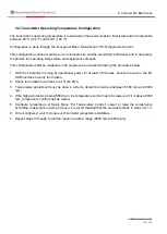
Page 102: ... the transmitter running at operational power for at least 30 minutes access the web or the PA USB interface to verify fan rotation 2 Check fan rotation for all fans in all of the PA s 3 Temperature adjustment must be done in order to obtain fan rotations between 5500 rpm and 6000 rpm 4 If the highest rotation is below 5500 rpm the temperature control has to be lowered If it is above 6000 rpm temp...

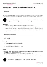
Page 103: ... inspections if there is a noise or an abnormal vibration in the fan located inside the equipment it should be replaced This same procedure should be followed for the frontal panel fans in the power drawers or the exciter module 2 Preventive Maintenance 2 1 Cleaning Initial steps Unplug the equipment from the power outlet Remove the side and top covers Disconnect all RF cables from the rear panel ...

Page 104: ...ons in the equipment and the irradiant system are correct 2 Verify if rain water is coming through the RF cables or water dripping from the shelter s ceiling 3 Verify all the air inputs and outputs of the equipment to make sure that they are not blocked 4 When you finish the visual inspection put the side covers back 2 3 Reading Verification Make all the possible measurements through the instrumen...

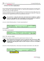
Page 105: ...tion This parameter is configured at the factory and should only be handled by a qualified technician and equipped with the appropriate test and measurement equipment Improper modification can cause serious damage to the Equipment Access the 22 24 1M00 Setup Menu Transistor Aging Adjustment Press ENTER The following warning appears Select YES and press ENTER The Bias values adjusts automatically a...

Page 106: ...106 108 E Compact MP BB3 Series Section 8 Attachments ...

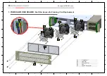
Page 107: ...05 04 04 03 03 02 03 04 05 05 1 POWER AMPLIFIER DRAWER Fan Filter Access for Cleaning Fan Replacement 01 Front Panel 02 Fan Filter 03 Fan protection 04 Fan 05 Fan DC Connector H G F E D C B A 8 7 6 5 4 3 2 1 H G F E D C B A 8 7 6 5 4 3 2 1 ...

Page 108: ...108 108 E Compact MP BB3 Series ...

Reviews: